Download
1 / 38
380 likes | 481 Vues
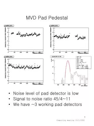
Detailed design and analysis of seismic pedestal and lead castle for the high-load-bearing structure, meeting Spanish standard NCSE-02 seismic parameters at Canfranc. The structure exhibits robustness and safety with steel ST-275 material and finite element analysis.

E N D
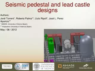
DRAFT NEXT-100 Authors: • Jordi Torrent*, Roberto Palma**, Lluís Ripoll*, José L. Perez Aparicio** * AMADE, University of Girona (Spain), ** Polytechnic University of Valencia (Spain) May / 08 / 2012 Seismic pedestal and lead castle designs
DRAFT NEXT-100 WORK STRUCTURE
DRAFT NEXT-100 Work structure 3D view of the work structure Top view of the NEXT-100 layout CASTLE CASTLE VESSEL CLEAN TENT EMERGENCY GAS DUMP • STATUS: The final drawings are fully finished and approved by Mr. José Jiménez on February 20, 2012. The first budget was 29.943,94€ + VAT. LSC has requested more budgets and construction will start when the budget is approved. • The main features: • Height : 1,270 [Meters] • Width and Height : 11x11 [Meters] • Live load : 1.500 [Kg/m2] and concentrated load : 300[Kg] • Material : Steel ST-275.
DRAFT NEXT-100 work structure: Manufacturing drawings
DRAFT NEXT-100 work structure: Manufacturing drawings
DRAFT NEXT-100 Seismic calculations, Spanish standard • Spanish standard NCSE-02 (BOE No. 244 – October 11, 2002) • Mandatory for all projects and structures if ab> 0.04g • At Canfranc, ab = 0.07g • NCSE-02 provides: • Seismic parameters at Canfranc • Elastic response spectra • Calculation methods
DRAFT NEXT-100 Spanish standard: Seismic Parameters at Canfranc
DRAFT NEXT-100 Spanish standard: Calculation methods • Response spectrum analyses • Calculate structure vibration modes • Maximum modal accelerations (relationships from the standard) • Maximum modal displacements • Dynamicanalyses (peak-by-peak) • Using synthetic (or real) earthquakes compatible with elastic response spectrum at Canfranc • Recommended in special structures
DRAFT NEXT-100 WORK STRUCTURE: Response Spectrum Analysis (750 Kg/m^2)
DRAFT NEXT-100 Work STRUCTURE: Safety Factors 0.30 0.30 0.36 0.36
DRAFT NEXT-100 SEISMIC PEDESTAL
DRAFT NEXT-100 Vessel supports Seismic pedestal: Design Guides of lead castle HEB-200 Beams Frames with rectangular beams Finite Element Analysis: Deformations, stress and buckling Wheel 8 Isolator seismic block Guide of lead castle HEB-200 Beams
DRAFT NEXT-100 SEISMIC PEDESTAL: Manufacturing drawings
DRAFT NEXT-100 Seismic Pedestal:Response Spectrum Analysis (Self Weight 85 Ton)
DRAFT NEXT-100 SEISMIC Pedestal: Safety Factors < 0.5 for all beams (must be < 1 according NCSE-02)
DRAFT NEXT-100 SEISMIC Pedestal: Peak-By-Peak Analysis; Input • “Synthetic” earthquake • Max. ax ≈ 0.2g [m/s2] • Max. acc. at Canfranc: ax ≈ 0.1g [m/s2], according to NCSE-02
DRAFT NEXT-100 SEISMIC Pedestal: Peak-By-Peak; Response at vessel beam supports
DRAFT NEXT-100 SEISMIC Pedestal: Peak-By-Peak; Response at vessel supports
DRAFT NEXT-100 LEAD CASTLE STRUCTURE
DRAFT NEXT-100 The steel boxes contain the bricks. Empty Full Steel boxes for the lead bricks Welding Welding 90º 200mm Bricks Bricks 200mm Bricks Inside of the castle Radius Inside of the castle Welding Welding
DRAFT NEXT-100 Lead castle structure Lead weight ≈ 58,2 Tons Frontal view of the castle Rear view of the castle Steel boxes for the lead bricks Structural steel shell Shielding steel structure Inside of the castle Outside of the castle
DRAFT NEXT-100 Vertical and horizontal mismatch of the stacking of the bricks. Wall of 2 Bricks. Inside of the castle Outside of the castle Structural steel shell External radiation External radiation Gaps between bricks 200mm Between 5 to 10mm Billet of lead or steel 100mm 100mm Lead bricks. 200mm
DRAFT NEXT-100 External and internal shielding structure. Rear view of the castle Shielding structure I steel beam External radiation Billet of lead about 5mm Outside castle 200mm Lead brick. 200mm Wall of2 Bricks. Inside castle Steel structural shell 2 to 3mm
DRAFT NEXT-100 Cutaway view of the shielding Details of shielding. Vessel supports
DRAFT NEXT-100 Cutaway view of the shielding Details of shielding Wall of the castle 200mm Billet of lead about 5mm Gap 10mm Billet of lead about 5mm Ground of the castle 200mm Foam joint
DRAFT NEXT-100 Internal shielding structure 40mm Bricks 50mm Structural steel shell Thickness ≈ 2or 3mm 2 or 3mm Internals structural beams Inside of the castle Structural steel shell Inside of the castle
DRAFT NEXT-100 Finite Element Analyses Deformations, stress and buckling
DRAFT NEXT-100 Two materials Inside of the castle Outside the castle Wall of2 Bricks. S-275 Steel Inside the castle Between 2 to 3mm Structural shell steel
DRAFT NEXT-100 Preliminary weight of the shielding structure
DRAFT NEXT-100 Removable external structure Option A: Steel beams In progress. Option B: Steel shells In progress. External shells of the lead walls. Manufacture with steel S-275 Supports of the lead walls. Manufacture with steel S-275
DRAFT NEXT-100 Removable roof of the lead castle Perimeter bolts Roof with Steel boxes full of lead bricks Roof weight ≈ 7 Tons
DRAFT NEXT-100 Junction between right and left castles 150mm 150mm Right castle Left castle 100mm 200mm 100mm Square holes for the passage of the pipes 101mm 150mm Inaccuracy in the axis
DRAFT NEXT-100 Shielding of the pipes and holes External radiation inside of the castle Shielding of the pipes and castle holes 150mm 150mm 101mm Bricks to be custom manufactured at LSC
DRAFT NEXT-100 Shielding of the pipes and holes External radiation does not access inside of the castle Our idea External radiation Shielding of the pipes and castle holes Lead weight = 2,4 Tons x 2 = 4,8 Tons
DRAFT NEXT-100 Shielding of the pipes and holes Cutaway lateral view of the castle Cutaway top view of the castle Shielding of Bricks Shielding of Bricks Elbow External radiation Elbow 200mm Inside of the castle
DRAFT NEXT-100 THANKS FOR YOUR ATTENTION
DRAFT NEXT-100 Thermal calculations