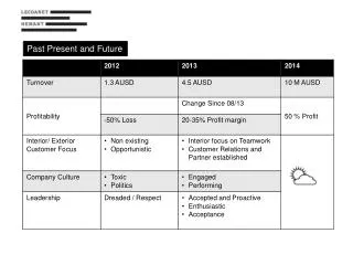
WCDMA Technology Past, Present and Future
WCDMA Technology Past, Present and Future. Part III: WCDMA Mobile Communication System. Part III: WCDMA Mobile Communication System. Overview of WCDMA WCDMA System Architecture WCDMA Protocols & Service Channels. WCDMA Basic (1/4). Goal :

WCDMA Technology Past, Present and Future
E N D
Presentation Transcript
WCDMA TechnologyPast, Present and Future Part III: WCDMA Mobile Communication System
Part III:WCDMA Mobile Communication System • Overview of WCDMA • WCDMA System Architecture • WCDMA Protocols & Service Channels
WCDMA Basic (1/4) • Goal : • an integrated seamless networkthat ensures global personal connectivity and enables access to broadband wireless multimediacommunications and services by anyone, from anywhere, at any time. (source: UMTS Forum) • Data Rate Requirements Source: ITU-R Circular Letter Edit: CHT-TL
WCDMA Basic (2/4) • Frequency band (ITU Allocation) • FDD : Downlink 1885-1980 MHz, Uplink 2110-2170 MHz (Extended Band: 806-960 MHz, 1710-1885 MHz, 2500-2690 MHz) • TDD : 2010-2025 MHz • Features of spread spectrum • Spread the information bits into the whole carrier space (white noise) • Channelisation by using the OVSF (Orthogonal Variable Spreading Factor)codes • Processing gain • Security • Anti-jamming
WCDMA Basic (4/4) • 3GPP • www.3gpp.org • WCDMA • FDD mode • TDD mode • Release • R99 (200003 freeze) • R4 (200103 freeze) • R5 (200203-06 freeze) • R6 (200306-12 freeze) • R7 (2004-)
WCDMA System Architecture (1/2) CS Domain PS Domain
WCDMA System Architecture (2/2) • Major Components to form the Network • UE (User Equipment) • UTRAN (UMTS Radio Access Network) • Node B and RNC • CN (Core Network) (R99) • Inherit the GPRS/GSM Core Network • SGSN/GGSN (GPRS) • MSC/HLR/VLR (GSM) • Two Switching Domain • Packet Switch Domain • Circuit Switch Domain
CN (Core Network) • MSC as upgraded CN for CS domain • SGSN as upgraded CN for PS domain • Existing network elements like HLR or GGSN will be modified and reused • Existing interfaces like E, Gn … will probably reused Ref: Tektronix
RNC (Radio Network Controller) • Control of one or more Node B • Interface with the CN (3G-MSC and 3G-SGSN) • Control the use and the integrity of the radio resources of UTRAN • Terminated RANAP, NBAP, RNSAP as well as RRC/RLC/MAC • The central element of an UMTS
Node-B (BS) • A logical node like BTS in GSM • Perform the air interface L1 processing • Responsible for transmission and reception in one or more cells to/from the User Equipment • Terminate the Iub interface, i.e. NBAP • RF power control • Control a number of cells Ref: Tektronix
End-to-End Bearer UMTS Bearer TE MT UTRAN CN (Iu EN) CN (GT) TE Radio Access Bearer TE/MT Local Bearer External Bearer CN Bearer Radio Bearer Iu Bearer Utra FDD WCDMA Bearer Services
UE Node-B RNC CN Uu Interface Iub Interface Iu Interface Applications Applications U CS PS U U CS PS U Application Protocol TCP UDP TCP UDP IP IP PPP PPP C C C C NAS Signaling CC SM CC SM NAS MM GMM MM GMM AS RRC RRC Iu Plane IuUP RANAP ALCAP RANAP IuUP AS Signaling PDCP RRC PDCP AAL2 SCCP Q.2630.1 SCCP GTP-U RLC RLC RLC Q.2150.1 MAC MAC MAC MTP3B UDP PHY PHY NBAP ALCAP Iub FP Iub Plane SSCF-NNI IP Radio Interface Radio Q.2630.1 AAL2 SSCOP Uu Plane Uu Plane Q.2150.1 AAL5 SSCF-NNI ATM ALCAP Iu Plane AAL5 ATM ATM Iub Plane Iub Plane Iu Plane WCDMA—Protocol Architecture (1/2)
WCDMA—Protocol Architecture (2/2) • Access Stratum • Non-Access Stratum • User plane protocols • Control plane protocols
W-CDMA UE Control Module Control Interfaces CS/PS Data Interfaces USIM Module CM Layer RABM Layer Control Plane User Plane MM Layer (Uu Interface) W-CDMA L3 RRC Layer W-CDMA L2 (Uu Interface) BMC Layer PDCP Layer USIM RLC Layer MAC Layer CPHY Transport Channels W-CDMA PHY SW/HW W-CDMA UE 端通訊協定架構
W-CDMA UE Control Module PS Data CS Data CBS Ctrl MM Ctrl CC Ctrl SM Ctrl SS Ctrl GSMS Ctrl USIM Module CM Layer RABM Layer CC Sub- layer SM Sub- layer SS Sub- layer GSMS Sub- layer CBS Sub- layer MM Layer MM Sub-layer GMM Sub-layer USIM UMTS NAS Nt GC DC BMC PDCP CS W-CDMA AS Protocol UE 端 NAS 通訊協定架構
W-CDMA NAS Protocol Nt GC DC BMC PDCP CS CPDCP RRC Layer CBMC BMC Layer PDCP Layer CRLC Radio Bearers RLC Layer Logical Channels CMAC MAC Layer UMTS AS CPHY Transport Channels W-CDMA PHY SW/HW UE 端 AS 通訊協定架構
Σ ⊕ ⊕ Σ j PHY 層基頻信號處理功能方塊 Transport Channel #1 Transport Channel #2 Transport Channel #N To RF CRC Attachment, Channel Coding, 1st Interleaving, Rate Matching CRC Attachment, Channel Coding, 1st Interleaving, Rate Matching Modulation CRC Attachment, Channel Coding, 1st Interleaving, Rate Matching Pulse Shaping Transport Channel MUX Scrambling CCTrCH I + jQ (DPDCH) Physical Channel Segmentation, 2nd Interleaving, Physical Channel Mapping PhCH #1 Spreading & Gain Weighting I PhCH #2 PhCH #3 Q PhCH #4 DPCCH
U-plane Radio Bearers Signalling Radio Bearers WCDMA Radio Interface Protocol Architecture (1/2) Control Plane User Plane L3 RRC Control BMC PDCP L2 Radio Bearers RLC Logical Channels MAC Transport Channels L1 PHY(W-CDMA) Physical Channels
WCDMA Radio Interface Protocol Architecture (2/2) • The radio interface protocol (access stratum) is layered into three protocol layers: • Layer 1: Physical Layer • Layer 2: Data link Layer --- split into two main sub-layers • Radio Link Control (RLC) • Medium Access Control (MAC) • Layer 3: Network Layer • Radio Resource Control (RRC)
RAB SRBs RLC MAC TrCH (DCH) TrCH (DCH) TrCH (DCH) TrCH(DCH) RB RB RB RB RB RB LgCH LgCH LgCH LgCH LgCH LgCH L1 PhyCH(RL) Radio Resource Mapping Concept • Signalling Radio Bearer (SRB): • RB#1~RB#4 are used for RRC signalling • Radio Access Bearer (RAB): • RAB is from the NAS viewpoint for User-plane services • one RAB may contain more than one RBs (RB#5~RB#31) • Logical Channel • information to be transferred (ITU-R M.1035) • Transport Channel • information transfer method • Physical Channel • corresponds to a specific carrier frequency, spreading code, and on the uplink, relative phase (0 or /2)
Logical Channel Control Channel BCCH PCCH CCCH DCCH Traffic Channel DTCH CTCH Logical Channels • Control Channel • BCCH : A downlink channel for broadcasting system information • PCCH : A downlink channel that transfers paging information • CCCH : A bidirectional channel for transmitting control information between a UE and the network • DCCH : A point-to-point bidirectional channel that transmits dedicated control information between a UE and the network • Traffic Channel • DTCH : A point-to-point channel, dedicated to one UE, for transfer of user information • CTCH : Point-to-multipoint unidirectional channel for transfer of dedicated user information for all or group of specified UEs
Transport Channel Dedicated Transport Channel DCH Common Transport Channel BCH PCH RACH FACH Common Packet Transport Channel CPCH Shared Transport Channel DSCH Transport Channels • Dedicated Transport Channel(DCH) • Carries all the information intended for the given user, including data and signals • Optimizes Radio Performance • Fast Power Control • Fast Data Rate Change on Frame Basis • Soft Handover • Needs some extra time to setup channel before using • Common Transport Channel • BCH : DL, relatively high power, low and fixed rate • PCH : DL, relatively high power, low and fixed rate, low power consumption • RACH/FACH : Open Loop Power Control or Fixed Power • Common Packet Transport Channel(CPCH) • Extension to the RACH • Fast Power Control without Soft handover • Shared Transport Channel(DSCH) • Similar to FACH • Fast Power Control without Soft handover
Physical Channels • Common Physical Channels: • Synchronization Channels (SCH, DL) • Primary Synchronization Channel (P-SCH) • Secondary Synchronization Channel (S-SCH) • Common Pilot Channel (CPICH, DL) • Common Control Physical Channels (CCPCH, DL) • Primary common physical channel (P-CCPCH) • Secondary common physical channel (S-CCPCH) • Indication Channel • Acquisition Indication Channel (AICH, DL) • Page Indication Channel (PICH, DL) • CPCH Access Preamble Acquisition Indicator Channel (AP-AICH, DL) • CPCH Collision Detection Channel Assignment Indicator Channel (CD/CA-ICH, DL) • CPCH Status Indicator Channel (CSICH, DL) • Physical Random Access Channel (PRACH, UL) • Physical Common Packet Channel (PCPCH, UL) • Dedicated Physical Channels: • Dedicated Physical Data Channel (DPDCH, DL&UL) • Dedicated Physical Control Channel (DPCCH, DL&UL)