Download
1 / 19
190 likes | 383 Vues
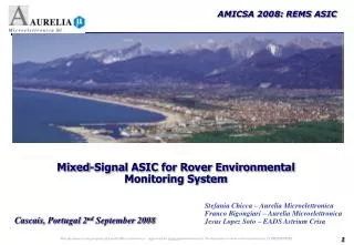
A 1553 Transceiver ASIC for Space Embedded Applications using a SOI Technology. A.Wagner EADS Astrium S. Chicca - Aurelia Microelettronica A.Colonna- Aurelia Microelettronica. Cascais, Portugal 1 st September 2008. Presentation Contents. MIL 1553 Transceiver status

E N D
A 1553 Transceiver ASIC for Space EmbeddedApplications using a SOI Technology A.Wagner EADS Astrium S. Chicca - Aurelia Microelettronica A.Colonna- Aurelia Microelettronica Cascais, Portugal 1st September 2008
Presentation Contents • MIL 1553 Transceiver status • Transceiver General Block Diagram and Features • Technology selection for a latch up free design • Architectural design choices to improve the transceiver robustness against TID • TID degraded models extraction and degraded-transceiver simulation campaign • Layout countermeasures to reduce effects of TID-induced leakage currents
MIL STD 1553 Transceiver The MIL STD 1553 IC transceiver has been designed by Aurelia and Astrium EADS, prime contractor, and placed and routed by Aurelia in the frame of the ESA Program “Europeanisation of MIL SDT 1553 Data Products” in X FAB 1.0mm HV SOI technology. Transceiver status: • I First run silicon functional with parametric non compliances recovered by FIB repair in I silicon • II Second run silicon showed recovery of all parametric non compliances • Co60 TID irradiation tests performed on First run by EADS Astrium and are planned for the Second run
Transceiver Design The transceiver design at architectural level has been conducted by taking into account the following requirements: • The transceiver has to be compliant with the STD 1553 physical layer specifications • The transceiver has to be latch-up free and it is used in space environment (TID tests performed up to 100Krad (Si) TID showed no deviation of the Electrical Characteristics up to 50Krad The rad-hardness of the design has been achieved by: • Technology selection: X-FAB SOI HV 1.0um CMOS process is latch up free • Architectural Design choices • Detailed Design and Layout choices • Extensive Simulation Campaign and Design Refining with TID-degraded models (in house built) based on TID tests performed on basic components We will present the transceiver design with special attention to the countermeasures undertaken to improve design rad-hardness and the results of the first run TID test campaign
Transceiver Key-Features • Transmitter section designed to couple with center tapped (GND) transformers according to MIL 1553 STD • High Impedance capability on transmitter (disable control pin TXINH) • Internal consistency check on digital control signals • Shaping network • Receiver section compliant with MIL 1553 STD, with internally generated threshold • Outputs RX and RXB generation programmable through RXINHB and RXSENS input pins • Internal filtering on receiver input waveforms to improve S/N ratio • 5V/3.3V compatible in/out digital interface thanks to dedicated power supply for digital outputs • TTL and LVTTL digital inputs • CMOS or LVCMOS digital outputs (depending on digital power supply level) • Less than 10mA current consumption when not transmitting • Latch Up Immune (SOI X-FAB 1.0um technology) • Radiation Goal compliant with space missions (50Krad achieved)
Architectural Design: transmitter Input Logic comparator with threshold derived from power supply to avoid logic input threshold shift due to TID effects Internal divers to provide the current capability to charge and discharge the power output transistor gate within the specified rise/fall times HV p-type Power output transistors Single blocking diode to block the current path towards the power supply related with high voltages induced from the bus Proposal for discussion: discuss current limitation feature against cross conduction transients
Power Transistors Selection To comply with the grounded center tap of the transformer (and avoiding internal charge pump) a p-mos structure is selected for the transmitter driver section. To comply with underground voltages at transmitter output pins, an HV structure (p-mos) is mandatory. However, HV structures are intrinsically weaker than 5V structures with respect to TID effects (trapped charges) due to field oxide on drift regions. Hence, design countermeasures to mitigate these effects have to be under taken. Positive trapped charges in the field oxide (300nm) may induce inversion on pdrift region causing a channel stop
First Countermeasure: design architectural Trade-off between open-loop and closed loop configurations show that closed loop driving concept allows to keep electrical parameters more stable against a wide range of environmental conditions (temperature, process spread, characteristics degradation as an effect of TID)
Second Countermeasure: simulation methodology TID-degraded models have been extracted for the most critical component in the design (p-mos HV driving transistor): for this purpose, TID irradiation test has been performed on basic structures provided by the foundry. Different TID-levels models have been built to fit the measured electrical characteristics. The main parameters inside the BSIM3V3 models which govern the characteristics degradation as an effect of TID are : m0 (cm2/Vsec): mobility factor nFactor : sub threshold drain current factor to take in to account for interface states We acted on both parameters to fit degraded models to the measured degraded characteristics.
Third Countermeasure: H-type layout Extensive use of H-type structures available in 1.0um HV SOI CMOS process reduces TID induced leakage. In H-type structures, the bird’s beak regions are not located on the low-doped well, but just over an high doped region of the well. This increases the potential needed to invert locally the well, as well the trapped charge amount needed to invert the channel and create the local leaking channel. The H-type structure builds a channel-stop for the leaking channel. Rectangular structure H-type structure
Receiver Architecture (Low Voltage Section) The receiver discriminates if the input filtered differential waveforms are inside the thresholds, above both thresholds, less than both thresholds. It acts as a window comparator. On the base of comparator outputs, and depending on input signals RXINHB and RXSENS logic status, the decodify to RX and RXB logic outputs is generated.
Receiver Block Diagram The input section of the receiver block needs to translate the input common mode from 0V (imposed by the transformer center tap to GND) to a 0V/5V input common mode, to allow that comparator operates correctly.
Radiation TID tests on the first RUN • Test performed up to 100 Krads using aCo60 source in 2 steps: • 0 to 28 Krads : 39 rads/h • 28 to 100 Krads : 94 rads/h • Use of a test structure in order to characterize the TID influence: • One sample (N°11: no irradiation) • 3 samples : (N°2,3,4 : power supplied) • 6 samples : not power supplied.
Radiation TID test Results • Test structure
Radiation TID test Results • Output Amplitude
Radiation TID test Results • Rise Time
Conclusion • XFAB SOI 1µ technology compliant with space mission environment. • It is possible to take into account the radiation effects during the design and the simulations. • It is possible to use a radiation structure to measure the TID in order to compensate the radiation effects by design.