Download
1 / 35
450 likes | 1.39k Vues
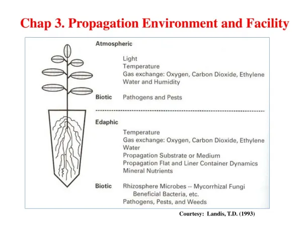
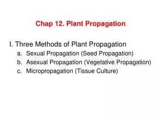
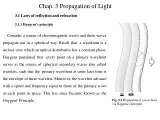
Chap. 3 Propagation of Light. 3.1 Laws of reflection and refraction. 3.1.1 Huygens’s principle.

E N D
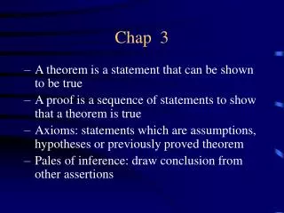
Chap. 3 Propagation of Light 3.1 Laws of reflection and refraction 3.1.1 Huygens’s principle Consider a source of electromagnetic waves and these waves propagate out in a spherical way. Recall that a wavefront is a surface over which an optical disturbance has a constant phase. Huygens postulated that every point on a primary wavefront serves as the source of spherical secondary waves also called wavelets, such that the primary wavefront at some later time is the envelope of these wavelets. Moreover, the wavelets advance with a speed and frequency equal to those of the primary wave at each point in space. This has since become known as the Huygens’ Principle. Fig. 3.1 Propagation of a wavefront via Huygens’s principle.
Fig. 3.1 shows a view of a wavefront , as well as a number of spherical secondary waves (wavelets), which after a time t, have propagated out to a radius of vt. The envelope of all these wavelets is then asserted to correspond to the advanced primary wave .
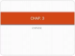
3.1.2 Snell’s Law and Law of Reflection and refraction We have seen previously that light is an electromagnetic phenomenon and already in the 16th century way before Maxwell a lot of studies were done of the interaction of light with water and with glass. The kind of experiment that were is depicted Figure 3.2. Incident θ1 θ3 reflected Air 1 2 !!1 !!1 θ2 refracted Water Fig. 3.2 Light at the interface of air and water
Suppose a beam of light strikes the surface between air and glass at an angle of incidence . Some light striking the surface is reflected with and angle of reflection . Some of that light goes into the water and is refracted with an angle of refraction There was a Dutch man called Snellys who in the seventheen century found three rules that govern the relationship between these three beams of light. The first one is that the incident, reflected and refracted beams are in the same plane, which is the plane of the board. The second thing that he found is that the angle which is called the angle of reflection is the same as the angle of incidence. That means the angle of incidence equals the angle of reflection is known as the law of reflection. The third one which is the most surprising one named after him is called snell’s Law is that if we go from air to water.
If we go from air to glass that will be much higher, like 1.5. He introduced the idea of index of refraction which we call n. Recall that for vacuum the index of refraction is 1, which is very closely to the index of refraction of the air. In water the index of refraction is approximately 1.3 and in glass depending upon what kind of glass you have is approximately 1.5. We can now amend this Snell’s law by writing n1 being the index of refraction of the medium where you are and n2 the index of refraction of the medium where you are travelling to. Is the law of refracrtion
3.1.2 Fermat’s principle The law of reflection and refraction and indeed the manner in which light propagates in general, can be viewed yet another entirely different and intriguing perspective afforded us by something called Fermat’s Principle. Fermat stated that the “The actual path between two points taken by a beam of light is the one that is traversed in the least time”. As we shall see in an little while this statement is somewhat incomplete. For the moment let us embrace it but not passionly.
Fermat’s principle in the case of reflection Fig. 3.3 Minimum path from the source S to the observer’s eye at P Fig. 3.3 depicts a point source S emitting a number of rays that are then “reflected” toward P. If we simply draw the rays as if they emanated from S’ (the image of S ), none of the distances to P will have been altered. But obviously, the straight-line path S’BP is the shortest possible one, which corresponds to This is the reflection law. And point B must be on this paper plane, which makes the incident beam SB, the reflected beam BP and the surface normal on the same plane. Fermat’s principle in the case of refraction
As an example of the application of the Fermat’s principle to the case of refraction, refer to Fig. 3.4, where we minimize t. The transit time from S to P, with respect to the variable x. The shortest transit time will then presumably coincide with the actual path. Hence or To minimize with respect to variations in , we set that is Fig. 3.4 Fermat’s principle applied to refraction. Using the diagram, we can rewrite the expression as
With so which is the refraction law or Snell’s law. Again SO,OP and the sample normal are on the same plane.
Suppose that we have a material composed of m layers, each having a different index of refraction, as in Fig. 3.5. The transit time from S to P will then be or where and are the path length and speed, respectively, associated with the ith contribution. Thus Fig. 3.5 A ray propagating through a multi-layered material. In which the summation is known as the optical path length (OPL) traversed by the ray. Clearly, for an inhomogeneous medium where is a function of position, the summation must be changed to an integral:
Inasmuch as , Fermat’s principle can be restated : light, in going from points S to P, traverses the route having the smallest optical path length.
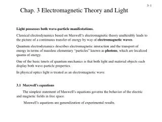
3.2 Electromagnetic approach of laws of reflection and refraction 3.2.1 Boundary conditions at a surface of a dielectric A dielectric is a substance that is a poor conductor of electricity but an efficient supporter of electrostatic fields Recall: L Gauss law-electric Ke1 Km1 dz Where =permitivity of the medium Positive direction Ampere’s circuital law Ke2 Km2 Where = permeability of the medium Fig. 3.6 Boundary conditions at a surface of a dielectric.
Recall Maxwell equations Among them we have Which means that This is a closed loop and you can choose any loop you want We are going to do the closed loop integral using figure 3.6 Now to make sure that we are at the boundary we make dz=0, that’s the trick! So if dz=0, then the surface equals zero so we have and then and Hence
So for a dielectric the first boundary conditions is: (3.8) For the three Maxwell equations left, we can derive the other boundary conditions for the dielectric which are (3.9) (3.10) (3.11)
3.2.2 Wave at an interface Suppose that the incident monochromatic light wave is planar, so that it has the form Assume that is constant in time, that is, the wave is linearly or plane polarized. The reflected and transmitted waves can be written as: and Here and are phase constants relative to and are introduced because the position of the origin is not unique. Figure 3.7 depicts the waves in the vicinity of the planar interface between two homogeneous dielectric media.
Fig. 3.7 Plane electromagnetic waves incident on the boundary between two homogeneous, isotropic, dielectric media.
The law of electromagnetic theory lead to certain boundary conditions. For example, the tangent of the electric field intensity to the interface must be continuous across it. In other words, the total tangential component of the electric field on one side of the surface must be equal to that on the other side. With being the unit vector normal to the interface, the boundary condition can be written as or Here is the unit vector normal to the interface. The above relationship must be obtained at any instant time and at any point on the interface (y=b). Consequently, , , and must have precisely the same functional dependence on the variables and , which means that
Inasmuch as this has to be true for all values of time, the coefficients of must be equal, so Clearly, whatever light is scattered has that same frequency. Furthermore, where terminates on the interface. From the first two terms we obtain Notice that since the incident and reflected waves are in the same medium, . is parallel to , that is, we conclude that Hence we have the law of reflection, that is
Again, from Eq. 3.19 we obtain and therefore is also normal to the interface. Thus , , , and are all coplanar. As before, the tangential component of and must be equal, and consequently But because , we can multiply both sides by to get which is Snell’s law.
3.2.2 Derivation of Fresnel equations We have just found that the relationship which exist amongst the phases of and at the boundary. There still an interdependence shared by the amplitudes , and which can now be evaluated. To that end suppose that a planar monochromatic wave is incident on a planar surface separating two isotropic media. and fields can be resolved into two components parallel and perpendicular to the plane of incidence and these components can be treated separately.
When you have an e.m wave coming in the direction of the and fields can be decomposed into two components one which is perpendicular to the plane of incidence and the other one parallel to the plane of incidence. That means each vector will have a perpendicular component and a parallel component . Each vector has an associated vector, it is married to a vector, and they go hand in hand. , and form a right handed system. The component associated to is
Case 1: perpendicular to the plane of incidence. θi θr θt Fig. 3.9: An incoming wave whose field is perpendicular to the plane of incidence field is parallel to the plane of incidence.
Now we can apply the boundary condition. The first one if you remember is that: represents the electric field in the medium one, which is the sum of the incident and reflected electric field. Represents the electric field in the medium two, which is the refracted electric field. So So now we can apply another boundary condition. We are going to leave the Ks because they equal a as far as we are concern. Km doesn’t in general deviate from one by any more than a few parts in 104 for example Km for diamond is 1-2.2X10⁻⁵
The continuity of the tangential component of requires that . Now we are going to use the relationship So we can replace by Equation (3.21) becomes So Now we can substitute so to have
Then rearrange to get (3.22) (3.23) For the transmission, we again start with the equation And eliminate using we then have (3.24)
Case 2: parallel to the plane of incidence. (3.25) (3.26) Fig. 3.10 Reflection and refraction of an incoming wave whose E-filed is in the plane of incidence. Further notational simplification can be made by using Snell’law whereupon the Fresnel equation for dielectric media become
(3.25) (3.26) (3.27) (3.28)
3.2.3 Interpretation of Fresnel equation This section is devoted to an examination of the physical implications of the Fresnel equations. In particular we are interested in determining the fractional amplitudes and flux densities which are reflected and refracted. i) Amplitude coefficients Let’s now briefly examine the form of the amplitude coefficients over the entire of θi –values. At nearly normal incidence (θi ≈ 0 ), the tangents in equation(3.27) are essentially equal to the sines in which case (3.29) (3.30)
In the limit as θi goes to 0, cosθi and cosθt both approach one and consequently (3.31) When it follows from Snell’s law that and so is negative for all values of θi . In contrast, starts out positive at θi =0 and decreases gradually until it equals zero when since is infinite. At normal incidence equation (3.24) and (3.26) lead rather straightforwardly, to (3.32) ii) Reflectance and transmittance Recall that the power per unit area crossing a surface in vacuum whose normal is parallel to the poynting vector is given by
Furthermore, the radiant flux density (W/m2) or irradiance is then This is the average energy per unit time crossing a unit area normal to (in isotropic media is parallel to ). In the case at hand let Ii, Ir and It be the incident, reflected and transmitted flux density respectively Accordingly, the portion of the energy incident normally on a unit area of the boundary per second is . Similarly, and are the energies per second leaving a unit area of the boundary normal to either side. The reflectance R is the ratio of the reflected over the incident flux (or power) i.e Fig 3.11 Reflection and transmission of an incident beam
While the transmittance T is the ratio of the transmitted over the incident flux and is given by Since the incident and reflected waves are in the same medium and In the same way assuming Where use was made of the fact that and
Let’s now write an expression representing the conservation of energy for the representation depicted in figure (3.11). In other word, the total energy flowing into area A per unit time must be equal to the total energy flowing outward from it per unit time Multiplying both side by c this expression becomes or But this is simply Where there is no absorption it is convenient to use the component forms, that is
3.3 Total internal reflection 4- Suppose that we have a light source imbedded in a glass, and we allow to increase gradually, as indicated in Fig. 3.12. As the angle of incidence increases, the angle of refraction increases. Moreover, since and Finally, when the refracted ray points directly along the interface. The angle of incidence giving this situation is called the critical angle It can be determined by Fig. 3.12 Internal reflection and the critical angle.
For angles of incidence larger than , there is no refracted ray and all the light is reflected. This effect is called the total internal reflection. The critical angle for our air-glass interface is roughly . Consequently, a ray incident normally on the left face of either of the prisms in Fig 4.15 will have and therefore be internally reflected. Fig. 4.13 Total internal reflection of light. Fig. 4.14 Total internal reflection