Download
1 / 14
140 likes | 178 Vues
This guide explores the evolution of FPGA design processes, from using TTL components to programmable devices like FPGA for faster prototyping and improved performance. Learn about different types of logic gates, Field Programmable Gate Array components, and the complexities of configuring FPGAs. Discover how software packages automate FPGA configuration, streamlining the design process. Dive into design capture methods, including VHDL, to enhance your FPGA projects. Improve your design efficiency today!

E N D
Lab13: FPGA Circuit RealizationCOE0501Dr. Steve JacobsYee-Wing Hsieh
Design Process Design process:(Labs 1-7) 1. Design entry (on paper) 2. Device mapping (TTL components) 3. Synthesis (proto-board) 4. Testing (logic analyzer) Design process:(Labs 9-12) 1. Design entry (schematics capture) 2. Device mapping (TTL components) 3. Testing (test vector simulation) 4. Synthesis (proto-board) 5. Testing (logic analyzer)
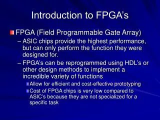
Improving Design Process Prototyping on Proto-board 1. Time consuming 2. Discrete TTL components (costly) 3. Wiring errors Programmable Devices (e.g. FPGA) 1. Fast prototyping 2. Highly integrated (less costly) 3. Good performance (speed/functionality)
Combinational Logic Gates 1. ROM (hardwire at mask level) 2. PROM (program once) 3. EPROM (UV erasable) 4. EEPROM (electrically erasable) 5. PAL/PLA/GAL (array of ANDs/ORs)
Field Programmable Gate Array Three Components: 1. Complex Logic Blocks (CLBs) 2. I/O Blocks 3. Interconnects Two Categories: 1. fine grain - a sea of gates/transistors 2. coarse grain - macro cells consist of flip flops and look up table (LUT)
Configuring FPGAs • Switches/Multiplexors determine the functionality • of CLBs, I/O blocks and interconnects. • Memory devices control the settings of switches/multiplexors • Configure FPGA by storing appropriate ‘1’s and ‘0’s to the • memory devices! • Problem: 1. Difficult to configure thousands/millions • of switch/multiplexor settings manually. • 2. Difficult to bind (map) logic functions • to PLD resources • Solution: Use software packages to perform binding and • configure FPGA automatically.
Design Capture 1. Logic (boolean expressions) 2. Schematic capture » 3. Hardware Description Language (e.g., VHDL/Verilog)
Designing with VHDL Design Process: (lab 13) 1. Design entry (VHDL) 2. Testing (VHDL test vector simulation) 3. Synthesis (FPGA, standard cell, full custom) 4. Testing (logic analyzer)