Download
1 / 1
10 likes | 156 Vues
Near Field Antenna Measurements for Cellular Phone Certification. Ahlia M. Tillman, John Rzasa, Bandar Hakim, Quirino Balzano, and Christopher C. Davis Department of Electrical and Computer Engineering. The Maryland Optics Group.

E N D
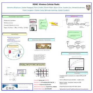
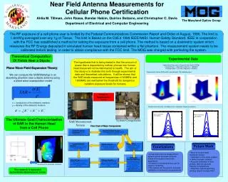
Near Field Antenna Measurements for Cellular Phone Certification Ahlia M. Tillman, John Rzasa, Bandar Hakim, Quirino Balzano, and Christopher C. Davis Department of Electrical and Computer Engineering The Maryland Optics Group The RF exposure of a cell phone user is limited by the Federal Communications Commission Report and Order of August, 1996. The limit is 1.6mW/g averaged over any 1g of Tissue. The limit is Based on the C95.4 1999 IEEE/ANSI Human Safety Standard. IEEE in cooperation with the FCC has established a method for testing the exposure from a cell phone. The method is based on a dosimetric system which measures the RF Energy deposited in simulated human head tissue contained within a flat phantom. The measurement system needs to be calibrated before testing in order to obtain compliance with the FCC limit. The MOG was charged with perfecting the system. Theoretical Computation Of Fields Near a Dipole Experimental Data The hypothesis that is being tested is that the amount of power that is deposited by cellular phones into human head tissue will not be detrimental to health. The aim of this study is to illustrate this both through experimental data and theoretical calculations. It will be shown that the SAR levels measured at frequencies of 900MHz and 1800MHz are well below the threshold for dangerous radiation exposure levels for humans Experimental area scan in lossy solution (scale in W/kg): Forward Power = 205 mW, Frequency = 1800MHz Forward Power = 277mW, Frequency = 900MHz Plane Wave Field Expansion Theory We can compute the SAR(Watts/kg) in an absorbing phantom near a dipole antenna using a plane wave superposition model Experimental Volume SAR profile (normalized to 1W radiated power): Views of Experimental Setup = conductivity of the dielectric medium = density of the dielectric medium Experimental line scan over dipole axis in respective frequency solutions. 5mm increments from bottom 5mm increments from bottom The Ultimate Goal:Characterization of SAR in the Human Head from a Cell Phone System Components SAR Measurement System . Flow Chart of Major Components Radio Frequency Generator: sends RF power to the antenna. Dual Directional Coupler: sends 0.1%(30dB down) of Forward and Reflected Power to the power meter. Power Meter: measures forward, reflected, and radiated power. Radiated Power = Forward Power - Reflected Power. Lossy Dielectric Solution: simulates the content of the human brain and is used to measure SAR values. Dipole Antenna: draws power from the RF generator via the coupler and radiates electromagnetic power. Future Work Conclusions • Move to human head dosimetric model. • Calibration of the entire system in terms of power radiated • Accurate calibration of field probes, take into account linearity considerations. • Determine optimal geometry, yielding largest average SAR. • A near-field antenna measurement system and an accurate computer model of the system have been assembled.. • A method of moments theory can be used for modeling. • The system can be used for accurate calibration of dosimetric measurements Computer Interface/LabView: the amplified voltages are then sent to the computer via a 12-bit I/O card, and from LabView the corresponding statistics are calculated.(e.g. SAR, radiated power, Ex, Ey, Ez) E-Field Probe: contains three orthogonal dipole sensors at the very tip that produces a voltage corresponds to the electromagnetic field near by. Voltage Amplifier: the three voltages from the E-Field probe are sent here and amplified through the circuit with a gain of 100. Courtesy of the University of Victoria This research is supported by the Mobile Manufacturers Forum