Download
1 / 51
510 likes | 685 Vues
Measurements of Barrel and EC HEX. R. Bates, M. Olcese, B. Gorski, QM for prototype builds. Contents. Details of the evaporative cooling system Measurements made: Barrel HEX EC HEX CERN Prototype QM-1 HEX Pressure drops over pipe work. The evaporative system in 175.

E N D
Measurements of Barrel and EC HEX R. Bates, M. Olcese, B. Gorski, QM for prototype builds R.Bates, QM
Contents • Details of the evaporative cooling system • Measurements made: • Barrel HEX • EC HEX • CERN Prototype • QM-1 HEX • Pressure drops over pipe work R.Bates, QM
The evaporative system in 175 • General design of system close to final design
Details of off-detector section R.Bates, QM
Detail of circuit tested • Volume and Danfoss meters for massflow measurements • Heat liquid after Danfoss to reach 35°C before HEX inlet • Manual heater control • PLC controlled proto-heater • ELMBs with PVSS monitoring plus some manometer duplication • Keller high pressure transducer before capillary R.Bates, QM
Enthalpy Diagram Psat=exp(T) Sub-cooling Pumping Condensation Expansion in the capillary Compression Boiling in the cooling circuit Subcooling increases efficiency, i.e. less flow required Final Heater R.Bates, QM
Why sub-cooling Cooling power = massflow x Enthalpy • Max Enthalpy at -25 °C = 102 J/g • No sub-cooling, liquid temp = 35°C • Power = massflow x 36 J/g : Endcap 9.6g/s, Barrel 14g/s • No sub-cooling, liquid temp = 20 °C • Power = massflow x 53.7 J/g : Endcap 6.5g/s , Barrel 9.5g/s • Sub-cooling to -10 °C • Power = massflow x 86.1 J/g • Massflow reduction up to 2.4 times! • Slightly lower as require Xu = 0.9 to cool inlet liquid in HEX • Endcap (35°C) = 5.7g/s, Barrel 7.8g/s • Reduce the change in massflow as a function of TlbHEX • No sub-cooling 50% increase in massflow • Sub-cooling <10% increase (small change in TlbCAP) R.Bates, QM
Pressure specifications 1bar pressure regulation Driven by -25 °C design T of on detector loop Max system pressure Driven by 40 °C max inlet T specification 350mbarpressure drop budget of on vapour side R.Bates, QM
HEX & massflow • HEX efficiency (and Massflow) must be sufficient to cool system with full power • Must cope with • TlbHEX = 20°C to 35°C • Sudden power changes in detector structures • Limited increase in Massflow as a function of • TlbHEX • Detector power • Vapour pressure drops to be as small as possible (50mbar) R.Bates, QM
Heat Exchangers • Design is different for the three sub-detectors due to different layout and geometrical constraints • All countercurrent type • Pixel: parallel type external. Al inlet and return tubes glued together over 1.5m. Simple design, possible with small power load • EC SCT: inlet tube is coiled in spiral inside the return tube over less than 0.4m. • Barrel SCT: parallel type internal. Two inlet tubes are routed inside the return tube over a length of 1.5m and parallel to the return tube axis R.Bates, QM
SCT EC heat exchangers • Several prototypes made • Final design qualified • Pressure drop budget is met • QMUL is making a final prototype with final tubes R.Bates, QM
Endcap HEX - designs • 1st failed due to boiling inside capillary • HEX1 – HEX3 failed due to low efficiency R.Bates, QM
Results with CERN HEX4 • Minimum massflow to remove nominal detector power of 346.5W found for HEX = 5.7g/s • Inlet liquid temperature of 35°C maintained through out • Massflow measured by volume meter • Massflow measurement checked with energy balance • Know inlet liquid and outlet vapour pressure/temperature • Know power into the system • Can calculate massflow R.Bates, QM
Baseline massflow = 5.7g/s for TlbHEX = 35°C, 100% power Minimum massflow
Results summary– CERN HEX4 Massflow Increase = 0.7% R.Bates, QM
Stability checks • Tests were performed to confirm that the system is stable • Ran for more than 2 hours without interference • Rapidly (less than 1 minute) increase detector power from 0 to 100% • Repeated measurements to confirm observations R.Bates, QM
0 to 100% power min massflow R.Bates, QM
+45deg V L -45deg V L Different HEX orientations • All with TlbHEX = 35°C, 100% power V • min massflow (g/s) 5.5 5.7 5.4 • PlbCAP (bara) 14.2 14.25 • TlaHEX (°C) -15 -13 -6.5 • Efficiency (%) .83 .80 .69 • Xi 0.13 0.17 0.22 • Xu 0.74 0.76 0.83
Only 2 capillaries open • Tested as some disks only have two circuits • Only 2 EC HEXs has 2 capillaries (disk 1) • Tested in +45deg as worse case • Efficiency of HEX reduced • Does not work for nominal massflow - now 3.98g/s • Minimum stable massflow = 4.4g/s • Same flow if use 2 x large capillaries • Could use 1large and 1small cap & increase pressure to test • TlaHEX = -20C, HEX eff = 0.92 • DP HEX V = 35mbar, DP on cylinder = 46mbar • Change in massflow 100%(T=35°C) to 0%(T=20°C) • 0.7% increase R.Bates, QM
QM-1 Inlet liquid pipe length reduced by 8% to 2764mm Stable at 98% power and massflow of 5.84g/s (2.5% above baseline 5.7g/s) Max massflow 8% above baseline massflow: (+45deg, 0%(T=20) = 6.06g/s) R.Bates, QM
Contra-flow Two liquid inlet pipes Length 1.5m HEX out of page 45 z Vapour in x Barrel HEX -45deg geometry R.Bates, QM
Results • Nominal massflow of 7.8g/s shown to remove nominal detector power of 504 W • Inlet liquid temperature of 35°C maintained through out • Stability checks performed • System measured for both ± 45deg • Tested with cooling loop & barrel 6 manifold • HEX vapour ΔP too high – but manageable R.Bates, QM
Results R.Bates, QM
Changes in massflow for changes in TlbHEX and power +45deg * Funny seen in the system. The operating conditions for a power cycle 100% to 0% power (TlbHEX = 35°C) resulted in a lower efficiency for the HEX and therefore lower massflows when compared to starting the system up. From start up the massflow for TlbHEX=35°C was 8.8 g/s. Not observed for -45deg geometry. R.Bates, QM
Efficiency increases with lower TlbHEX Xi Xu 20C 0.15 0.78 35C 0.38 0.99 R.Bates, QM
Highest efficiency up to 75% power – 378W TlbHEX=35C 75% power Massflow = 8.6g/s R.Bates, QM
Stability 0 – 100% power TlbHEX = 35C TvaHEX = 14C TlaHEX = 9.5C TvbHEX = -25C R.Bates, QM
2hour run R.Bates, QM
System only slightly affected at 75% power Vq=0.75 Vq=0.98 R.Bates, QM
Barrel HEX with cooling loop R.Bates, QM
Barrel HEX with cooling loop R.Bates, QM
Barrel HEX/Cooling loop test • Tested HEX with real cooling loop • HEX performance the same with cooling loop as with dummy load • Cools first and final module • Pressure drop over cooling loop considerable – results in evaporation temperature changes • ΔP less for lower detector power and lower inlet liquid temperature R.Bates, QM
Cooling loop Press & Temps R.Bates, QM
P in loop & manifold 100% power Pman = 280mbar Ploop = 540mbar Ptotal = 820mbar R.Bates, QM
Smooth increase in P as function of outlet vapour quality R.Bates, QM
P for TlbHEX = 20ºC • For m=7.8g/s • Vapour quality reduced • Pressure drop reduced • Still very high • Tevap reduced • T < 3ºC • NOTE • If reduce massflow then VQ increase, P and Tevap rise R.Bates, QM
Summary of HEX performances Need more liquid at the outlet (higher efficiency) for stability 50% more capacity Min flow cooling 100% of power with stable load transients 0%-100%-0% R.Bates, QM
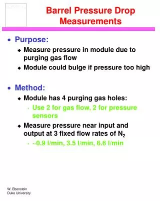
Pressure drop measurements • Pressure drops measured for: • Inlet pipe work ID = 4 mm, Length = 10.8 m • Outlet pipe work ID = 8 mm, Length = 6 m • Final design of Endcap On-cylinder pipe work • Prototype EC and Barrel Heaters • HEX of each design: Liquid inlet & Vapour return • Barrel cooling loop • Barrel HEX to manifold pipe work • Final pipe work sizes predicted for • heater exhaust to PPF1/PPF2 • PPF2 to PPF3 (PR on racks) R.Bates, QM
Extra slides R.Bates, QM
Photos BPR The main cooling rig R.Bates, QM
Condenser, volume meter, PLC R.Bates, QM
Power supplies for cooling loop heaters R.Bates, QM
Barrel cooling loop pictures Final cooling loop Barrel 6 manifold Barrel 3 pipe run manifold to HEX 36 ceramic heaters R.Bates, QM
Pictures Capillary into loop Pressure measurements just after capillary Press sense 5cm after manifold on exhaust Temperature sensors on pipe and on heaters Insulations around temp sensors R.Bates, QM
Barrel HEX & cooling loop • HEX at -45deg • Loop horizontal R.Bates, QM
EC QM HEX prototype • First QM EC HEX at CERN R.Bates, QM
Pressure specifications • High input P : MinPinlet > Psat(T=40°C) = 12.8bara MinPinlet= 13bara • Psat(T=35°C) = 11.3bara MinPinlet= 11.5bara • Low evaporating pressure : P(T=-25°C) = 1.67bara • Pressure drops • Liquid side • Capillary to PR = 1bara • PR to cooling rack = 1bara • PR range (for flow regulation) = 1bara Pressure from liquid pump = 16bara • Vapour side • Pmin at inlet of BPR = 1.3bara • Pressure drop from detector structures to BPR = 350mbara • Pressure drop includes drop along Heater, (budget = 50mbar), HEX, on-cylinder pipe work, and rest of pipe work to BPR. • Higher massflow implies higher pressure drops in system • BIGGER pipes, bigger Heater etc • And more powerful Heater R.Bates, QM
Number of circuits and capacity R.Bates, QM