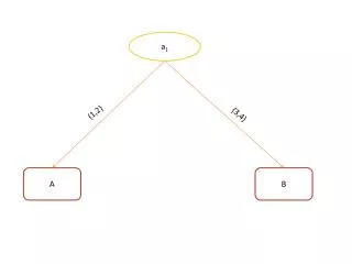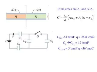
If the areas are A 1 and A-A 1 .
170 likes | 747 Vues
If the areas are A 1 and A-A 1. C 123 2.4 µF, q = 28.8 µC C 2 C 24 = 12 µ F C 1234 = 3 µF q =36 µC. The force on a filling dielectric as it is inserted between the parallel plates of a capacitor. x. L. With the battery connected, U 1 = ½CV 2. With the battery disconnected,

If the areas are A 1 and A-A 1 .
E N D
Presentation Transcript
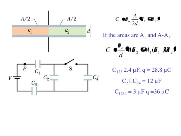
If the areas are A1 and A-A1. C123 2.4 µF, q = 28.8 µC C2C24 = 12 µF C1234 = 3 µF q =36 µC
The force on a filling dielectric as it is inserted between the parallel plates of a capacitor. x L With the battery connected, U1 = ½CV2 With the battery disconnected, U2 = Q2/2C With the battery connected, since x is increasing downwards, a negative force is upwards, pushing the dielectric away. With the battery disconnected, the force is positive and pointed downwards, pulling in the dielectric. The force is proportional to (κ-1) and inversely to L.
Chapter 26 Current and Resistance In this chapter we will introduce the following new concepts: -Electric current ( symbol i ) -Electric current density vector (symbol ) -Drift speed (symbol vd) -Resistance (symbol R ) and resistivity (symbol ρ ) of a conductor -Ohmic and non-Ohmic conductors We will also cover the following topics: -Ohm’s law -Power in electric circuits (26 - 1)
HITT The plate areas and plate separations of five parallel plate capacitors are capacitor 1: area A0, separation d0 capacitor 2: area 2A0, separation 2d0 capacitor 3: area 2A0, separation d0/2 capacitor 4: area A0/2, separation 2d0 capacitor 5: area A0, separation d0/2 Rank these according to their capacitances, least to greatest. a. 1,2,3,4,5 b. 5,4,3,2,1 c. (524) ,(13) d. 4, (12), 5,3 e. None of these
A B (26 - 2)
conductor + q i conductor - q i (26 - 3)
conductor A conductor - q A i + q i (26 - 4)
i - R + V (26 - 6)
i - + V (26 -7)
V (26 - 13)
hitt To store a total of 0.040 J of energy in the two identical capacitors shown, each should have a capacitance of: • A. 0.10 μF • B. 0.50 μF, 0.10 μF • C. 1.0 μF • D. 1.5 μF • E. 2.0 μF