Download
1 / 39
410 likes | 860 Vues
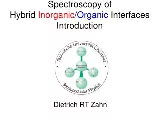
Spectroscopy of Hybrid Inorganic / Organic Interfaces Introduction. Dietrich RT Zahn. w. h. e. e. Semiconductor Physics – Activities in Chemnitz. Growth: (Organic) Molecular Beam Deposition in Ultra-High Vacuum (Metal-Organic) Vapour Phase Deposition. Surface Science:

E N D
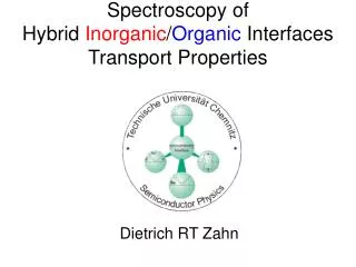
Spectroscopy of Hybrid Inorganic/Organic InterfacesIntroduction Dietrich RT Zahn
w h e e Semiconductor Physics – Activities in Chemnitz Growth: (Organic) Molecular Beam Deposition in Ultra-High Vacuum (Metal-Organic) Vapour Phase Deposition Surface Science: Photoemission Spectroscopy (UPS and XPS) X-ray Absorption Fine Structure (NEXAFS) Auger Electron Spectroscopy (AES) Low Energy Electron Diffraction (LEED) Inverse Photoemission Kelvin Probe (CPD) Electrical Measurements: Current-Voltage (IV) Capacitance-Voltage (CV) (Deep Level) Transient Spectroscopy Semiconductor Interface w h Optical Spectroscopy: Raman Spectroscopy (RS) Photoluminescence Spectroscopic Ellipsometry (SE) UV-vis Infrared Spectroscopy (IR) Reflection Anisotropy Spectroscopy (RAS)
Major Research Areas I. Inorganic/Organic Hybrid Structures II. Low Dimensional Semiconductor Structures, in particular Quantum Dot Superlattices; Cooperation with the Institute of Semiconductor Physics in Novosibirsk III. Wafer Bonding; Arrays of Micromechanical Sensors and Actuators, SFB 379
Designing Inorganic/Organic DEvices EU Funded Human Potential Research Training Network Contract No. HPRN-CT-1999-00164, www.tu-chemnitz.de/diode
Metal I Organic Interlayer GaAs(100) V DIODE Project (iv) The Interface between the Organic Molecules and the Metal (v) The Overall Device Performance (iii) The Organic Molecular Film (ii) The Interface between GaAs Substrate and Organic Molecules (i)GaAs Substrate Surface D. R. T. Zahn, TU Chemnitz
Molecular Control of III-V Diodes Metal/III-V Semiconductor contacts High frequency application e.g. Mixers, Modulators • Metal/organic/InPA. Böhler et al. Mater. Sci. and Eng. B 51 (1998) 58: Rectifying behavior: Superior to commercial diode: High frequency limit: 42 GHz Challenge: lowering operating voltage. Organic thin interlayer Dietrich RT Zahn, TU Chemnitz
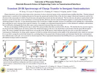
Technology at TU Braunschweig OMBD OMBD - PTCDA(10nm) - Ag(200nm) Lift-off in 20%NaOH ------------------------------------------------------ Ag PTCDA Lift-off Ag contact Active area SiO2 layer Au/Ni/Ge n-- GaAs/ n+- GaAs substrate 100 m
Ag/PTCDA/GaAs Ag/GaAs PTCDA modified Ag/GaAs(100) Schottky Contacts • 30 nm PTCDA interlayer. • Reverse bias/Low forward bias • Increase in current ( 1000) • Decrease in barrier height ( -150 meV) • High forward bias • Deviation from thermionic emission. 3,4,9,10-Perylenetetracarboxylic dianhydride ( C24H8O6) Dietrich RT Zahn, TU Chemnitz
Organic Semiconductors • Primary interest: Organic LEDs and displays. • Low cost plastic electronics. • Modification of semiconductor devices. • Polymers • Long molecular chains, „Spin-Coating“. • Monomers • Extended and conjugated -electron system. • Phthalocyanines, perylene derivatives. • Organic Molecular Beam Deposition (OMBD). • (S. R. Forrest, Chem. Rev. 97 (1997) 1793)
I Organic Interlayer GaAs(100) V Organic field-effect transistors Displays (Kodak) Electrically driven organic lasers Organic semiconductors Organic/Inorganic Microwave Diodes Metal Plastic solar cells Organic-modified Schottky Diodes G. Salvan, TU Chemnitz
Substrate Multilayer Device Structure - Electron Injection Electrode + Electron Transporting Layer Light Emitting Layer Hole Transporting Layer Hole Injection Electrode Light
Vacuum level Ea + + eFa eFc Oe + + fe Ip Cathode fh Oh - - Anode - - P-I P-2 Bilayer Structure Advantages - Optimize injection of each carrier type separately : Balance charge injection - Optimize mobility of each carrier type separately - Control transport by energy level offsets at the heterojunction interface : confinement of charges ; optimize charge recombination - Keeps exciton decay away from electrodes : minimize electrode quenching
Organic Semiconductors Molecular / Polymeric Materials Van-der-Waals Bonds no dangling bonds Conjugated Materials (extended (delocalized) p-electrons) ‘Bandgap’ of 1.5 to 3 eV
Delocalised -Electron System Benzene
Energy E / eV 3,0 2,5 2,2 2,05 1,7 UV IR 410 495 560 620 700 Wavelength / nm 1 eV = 1,60210-19 J 1 kT = 0,025 eV (T = 300 K) 1 nm = 10-9 m = 10 Å
Inorganic semiconductor: wide bands and delocalized states - - CB small exciton binding energy Transport gap ~ optical gap VB + + Energy levels and transport: Bloch states and single-electron approximation • Organic molecular solid: small transfer integral between molecules; charge carrier = molecular ions; electronic polarization + molecular relaxation - - LUMO Single-particle or Transport gap Optical gap + + HOMO On-molecule neutral excitation strong e-h coulomb interaction Ground state of neutral molecule Molecular ions Transport gap – optical gap = exciton binding energy
! Organic Semiconductors Semiconducting properties:
„small molecules“ Polymers e.g. PTCDA: 38 atoms ! Compare: Inorganic semiconductors: typically 2 atoms/unit cell e.g. Silicon (Si) or Galliumarsenide (GaAs)
a a -6T -4T S S S S C60 S S S S S S Pentacene Tetracene Some Semiconductors a-quartertiophene a-sexithiophene p-conjugated Molecules (oligomers) Transport p-p* overlap
Perylene derivatives PTCDA:3,4,9,10- Perylenetetracarboxylic dianhydride DiMe-PTCDI:3,4,9,10- Perylenetetracarboxylic diImide C24H8O6 C26H14O4N2 + Phthalocyanines at UWA DRTZ TUC
PTCDA Crystal Experimentally derived geometry via X-ray analysis 3.21 Å c b b c • two molecules per unit cell • - and - phases - PTCDA - PTCDA
d=3.21 Å PTCDA crystal structure 3,4,9,10,-Perylene TetraCarboxylic DiAnhydride (C24H8O6) • Single crystals: • double sublimation of PTCDA powder needle - like crystallites (50 200 2000 m3) • - phase • Thin films: • 40 nm PTCDA/ H-Si(001) grown at Tsub = 410 K polycrystalline structure with the domain size below 500 nm • dominantly - phase • monoclinic structure (C2h): 2 molecules per unitcell c’ b
PTCDA/GaAs(100)-S:2x1 Topography Tsubstrate =360 K Atomic Force Microscopy Preferred orientation of crystallites – one edge to GaAs(110). Tsubstrate =410 K Tsubstrate =295 K
Crystal Structure - Anisotropy Herringbone-Structure van-der-Waals (attraction) Pauli-Principle (repulsion) Layered Semiconductor Anisotropy spar / sper ~70 ~3 spar1 / spar2 ~1.5 ~1.5 Thiophenes Acenes Tetracene
z x y PTCDA 3,4,9,10- Perylenetetracarboxylic dianhydride (C24H8O6) Alq3 Tris(8-hydroxyquinoline)Aluminum Al(C9H6NO)3 2.21eVOptical absorption(exp)2.7eV D2h Symmetry C3v (Facial-isomer ) 108 internal vibrational modes: Raman active: 19Ag+18B1g+10B2g+7B3g 150 internal vibrational modes: Raman and IR active Thin films: mixture of two crystalline phases: monoclinic space group
Organic Vapor Phase Deposition:The Concept • 0.1 - 5 Torr • Vapor Phase • External Sources • MFC Source Control • Directed Carrier Flow • Hot chamber walls • Large Substrates, Webs • Efficient Materials Use • Low Source Cross-Contamination • High Control of Doping • Higher Throughput with courtesy of UDC
OVPD: R&D Deposition System Design 4 source barrels Carrier Gas Inlets Thickness monitor 4-zone heater Glass chamber Standard fittings Temperature probes To Pump Rotating cooled holder Clean Deposition Chamber Mechanical Shutter Isothermally heated source Efficient & Controlled Evaporation: 0.3 grams of material last > 150 films with courtesy of UDC
OVPD: System Overview Computer Control GMS (Gas Mixing System) Reactor
Ink jet printing INK With a modern ink jet printer it is possible to make printed circuits with a dissolved polymer up to 2400 dpi
Paper based electronic The dream: Organic circuits printed on paper by offset printing, ’soft’ lithography • Paper is a cheap and friendly to the environment • (Theoretically) very high speed of production • Cheap electronics: • Sensors in food containers • Electronic magazines • Billboards, simple animations • Wireless communication, prize tags