LRFD Design of Compact Beams: Factors and Examples
120 likes | 132 Vues
Learn about LRFD design principles for compact beams including lateral torsional buckling, moment gradient factors, and bending of compact sections. Explore practical examples and calculations.

LRFD Design of Compact Beams: Factors and Examples
E N D
Presentation Transcript
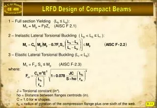
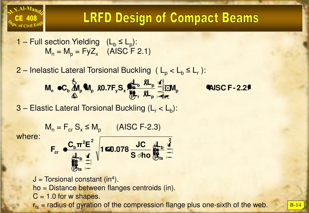
LRFD Design of Compact Beams 1 – Full section Yielding (Lb ≤ Lp): Mn = Mp = FyZx (AISC F 2.1) 2 – Inelastic Lateral Torsional Buckling ( Lp < Lb ≤ Lr ): 3 – Elastic Lateral Torsional Buckling (Lr < Lb): Mn = Fcr Sx ≤ Mp (AISC F-2.3) where: J = Torsional constant (in4). ho = Distance between flanges centroids (in). C = 1.0 for w shapes. rts = radius of gyration of the compression flange plus one-sixth of the web. B-14
(Cb) Moment Gradient Factor Equations (F 2.2) & (F2.4) for compact beams affected by lateral torsional buckling, require the introduction of the “Moment Gradient Factor” (Cb) for non-uniform bending moment values between the lateral bracing points for (Lb). AISC provides value for Cb as: The effect of Cb on Nominal Strength is shown below: B-15
(Cb) Examples on Moment Gradient Factor Example B - 5 Determine (Cb) for a uniformly loaded, simply supported beam with lateral supports at its ends only. Solution B-16
(Cb) Some Examples on For unbraced cantilever beams, AISC recommends the value of Cb = 1.0. A value of Cb = 1.0 is always conservative and represent uniform banding throughout the unbraced length (Lb), (See Table 3-1) AISC. B-17
Example on Bending of Compact Sections Example B - 6 • Determine the design strength (b Mn) for W14 68 made of A-572-Gr50 steel and: • Continuous lateral support. • Unbraced length = 20 ft, Cb = 1.0 • Unbraced length = 20 ft, Cb = 1.75 Solution A) Check compactness: web is always compact ! Mn = Mp = FyZ = 20 115 = 5750 in·k = 479 ft·k. b Mn = 0.9 479 = 431 ft·k. B) B-18
Continued: Since Lp < (Lb = 20 ft) < Lr Equation F – 2.2 controls: b Mn = 0.9 316.25 = 284.6 ft·kip. • For Cb = 1.75, other conditions unchanged: • Mn = 1.75 316.25 = 553.4 ft·k. • Since Mn ≤ Mp, • then Mn = Mp = 479 ft·k • bMn = 0.9 479 =431 ft·k. B-19
w L = 20 ft Design of Un-braced Beams Example B - 7 A simply supported beam of span = 20ft is to carry static dead load of (1.0 k/ft) and a live load of (2.0 k/ft) in addition to its own dead weight. The flange is laterally supported at support points only. Select the most economical W shape using A572-Gr50 steel. Solution Estimate self weight = 0.06 k/ft. Wu = 1.2 x 1.06 + 1.6 x 2 = 4.47 k/ft Check your selection: From Load Factor Design Selection Table 3.2 in AISC (page 3-17) : Zx = 77.9 in3 , Lp = 8.76 ft , Lr = 28.2 ft. Determine (Cb) for UDL = 1.14 (see B-16) bMn Mu bMn 224 k.ft Enter Beam Design Moments Chart at AISC for Lb = 20 ft, and bMn = 234, select: W12 x 53 (page 3.126 but for Cb = 1.0) B-20
Design Problem Contd.. Since Lp<(Lb=20 ft) < Lr then : equation ( F-2 – 2b AISC) where Cb = 1.14 Mp = FyZx = 50x77.9 = 3895 k. in = 324.6 k·ft. Sx = 70.6 in3 bMn = 0.9 x 292 = 262.7 (Mu = 223.6 k·ft) OK B-21
Bending Strength of Non-compact Sections As noted earlier, most W,M & S shapes are compact for Fy = 36 ksi and Fy = 50 ksi , very few sections are non-compact because of their flanges, but non are slender. The effect of non-compact flange is recognized in the AISC as the smaller value of LTB (AISC F 2.2) and where B-22
Non – Compact Flange Section Example B - 8 A simple supported beam with span = 45 ft is laterally supported at ends only , and is subject to the following service loading: D.L. = 0.4 k/ft ( including self wt.) L.L = 0.7 k/ft Is W 14 x 90 made of A572-Gr50 steel adequate? Solution Wu = 1.2 x 0.4 = 1.6 k·ft B-23
Non – Compact Flange Section Contd. p < < r The shape is non-compact. Section properties: Zx = 157 in3 , Sx = 143 in3 (properties 1) Lp = 15.2 ft, Lr = 42.6 ft (Table 3.2 p. 3.16) • Now we check the capacity due to LTB: Lr < ( Lb = 45 ft) Elsatic LTB controls bMn = 0.9 x 638.2 = 574.4 Mu OK B-24
Non – Compact Flange Section Contd. Mn = Fcr Sx Mp (probably this beam is O.K.). bMn = 398.7 k. ft < 405 k·ft B-25