Download
1 / 11
110 likes | 264 Vues
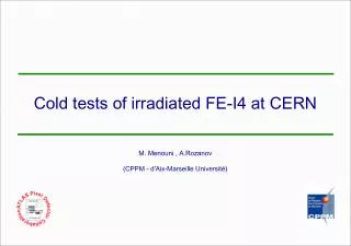
FE-I4 irradiated chip tests at low temperature. M. Menouni , P . Breugnon , A.Rozanov (CPPM - d'Aix-Marseille Université). Introduction. The Single board FE-I4-B number 165 was irradiated in 2012 at CERN PS with 24 GeV protons close to the region of end of columns

E N D
FE-I4 irradiated chip tests at low temperature M. Menouni, P. Breugnon, A.Rozanov (CPPM - d'Aix-Marseille Université)
Introduction • The Single board FE-I4-B number 165 was irradiated in 2012 at CERN PS with 24 GeV protons close to the region of end of columns • This region of the chip received a total dose of 400 Mrad • Last presentation -> the threshold is tuned at low temperature for a threshold of 3000e- for the whole pixel array • Noise distribution observed at room temperature (25°C) at low temperature (- 26 °C) • Results are obtained with the default configuration where : • PrmpVbp = PrmpVbpRight = PrmpVbpLeft=43 • Amp2Vbpf=100 • Amp2VbpFol=26 irradiated FE-I4 tests at low temperature
Tests results at room temperature • All the pixels of the array are tuned to a threshold level of 3000e • The noise distribution shows clearly that the mean noise level in the irradiated region (100 e rms) is higher than the noise in the non irradiated pixels (150 e rms) irradiated FE-I4 tests at low temperature
S-Curves at room temperature • Individual pixel S-Curve at 27°C • Pixel (col 17-row 26) situated outside the irradiated region : 102 e RMS • Pixel (col 39 – row 273) inside the irradiated region shows a noise level of 166 e RMS irradiated FE-I4 tests at low temperature
Tests results at low temperature (-26°C) • All the pixels of the array are tuned for the threshold level of 3000e • The same level of noise in irradiated and non irradiated region (~200e RMS) • The increase of the noise because of the low temperature is higher than the increase caused by the irradiation ? irradiated FE-I4 tests at low temperature
S-Curves at low temperature (-26°C) • Individual pixel S-Curve at -26°C • Pixel (col 17-row 15) situated outside the irradiated region : 228e RMS. Noise over-estimated by the fit curve • Pixel (col 39 – row 273) inside the irradiated region shows a noise level of 200e RMS • The transition part of the curve is less regular than for room temperature • Configuration parameters to change for working at low temperature ? irradiated FE-I4 tests at low temperature
Tests results at low temperature (-26°C) • The noise level of the pixels belonging to the two right DC is less than 100e RMS. The column in the left shows also a lower noise • The noise level is 84 e RMS for the pixel (col 78, row 138) • There is any particular bias for this DC ? irradiated FE-I4 tests at low temperature
Noise Occupancy • The target threshold is 3000e • The threshold depends on the Amp2Vbpf • This threshold is re-evaluated and corrected for Amp2Vbpf changing • Increasing PrmpVbp Help to reduce the noise occupancy • Measurements take a lot of time. It is necessary to finalize this measurement ? irradiated FE-I4 tests at low temperature
DC level of out1 • DC levels measured for out1, out2 and vtheff through the output Out_An associated to the analog mux stage. Colpr_Addr used to select one output among 32. Coulmnsare numbered 0 to 79 • Pixels situated in the most irradiated zone have lower out1 DC level • The lowest out1 DC value is 230 mV for the column number 22. irradiated FE-I4 tests at low temperature
DC level of out1 • Abderrezak measurements on the chip Ch27 show a lower DC value (80mV to 120 mV) compared to the chip 165 (230 mV to 280 mV) • This explain Why the chip 162 can be tuned even for the PrmpVbp default value Ch27 chip irradiated FE-I4 tests at low temperature
Perspectives • Next tests on the chip 165 irradiated to 400 Mrad (default config): • Finalize Noise Occupancy measurements versus Amp2Vbpf (= 40, 100, 255) for PrmpVbp = 43 and PrmpVbp = 96 • The target threshold is 3000e and this threshold is re-evaluated forAmp2Vbpf value changing • Use a higher statistics for Noise Occupancy • IV transfer function at the PrmpVbp Pad at 25°C and -26°C. This test will allow estimate the gate leakage influence on the bias of the preamp • First measurements at room of the chip 162 at room temperature show that it is still alive • We will try to find a good configuration at room temperature and do tests for low temperature irradiated FE-I4 tests at low temperature