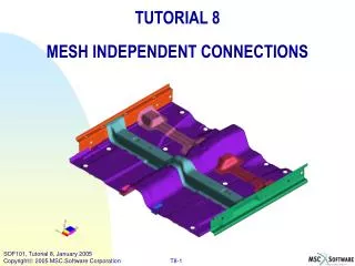
Mesh Morph 2.0 Tutorial
Mesh Morph 2.0 Tutorial. Mesh Morph has 3 main tools (Methods); 2.5D Hex Mesh, Copy Pave Mesh, and Loft Hex Mesh. The main purpose of the tool is hex meshing and the 2.5D Method is the primary tool for that.

Mesh Morph 2.0 Tutorial
E N D
Presentation Transcript
Mesh Morph has 3 main tools (Methods); 2.5D Hex Mesh, Copy Pave Mesh, and Loft Hex Mesh. The main purpose of the tool is hex meshing and the 2.5D Method is the primary tool for that. • 2.5D Hex Mesh: Extrudes hex elements from a starting shell mesh along a path bounded by shell elements. • Copy Pave Mesh: Copies a Paved mesh from one surface/face to a topologically identical one. • Loft Hex Mesh: Lofts a Hex mesh between a paved trimmed surface and a topologically identical unmeshed trimmed surface.
Definition of a 2.5 D solid or Mesh region. A 2.5D solid has an obvious extrusion path through the solid/region. Through this extrusion path, the cross section can change shape, but the topology must remain constant. That means that the number of holes and edges must remain the same. As a result of this limitation, all side faces or surfaces will be 4 sided. Blind Hole Tapered Press fit shaft with shear pin Fillet Area of a larger part Not a 2.5D solid/region, but can be modified to be one. Not a 2.5D solid/region, but is made up of 4 simple 2.5D regions. Shape changes from square to round. Hole Changes from round to square. Section of a turbine blade with cooling channels Not a 2.5D solid/region Modified solid from above is now a 2.5D solid This metal fitting is NOT a 2.5D region, but can be divided into 7 different 2.5D meshing regions.
2.5D Hex Mesh This feature is the main purpose of the tool and the main focus of this document. You start with just shell elements, typically on faces of a solid, but no solid is required. All faces will be meshed accept the end face (End Surface). Smoothing parameters that control the smoothing of each layer. Normally the defaults should be used. Smoothing strategies if either starting mesh (Bottom Elements) or ending face (End Surface) is significantly convex or concave. Starting mesh, typically a trimmed surface or complex face of a solid. Input is Either elements or meshed face(s)/surface(s). Sides of the 2.5D meshing region. The mesh must be a structured iso-mesh type mesh. Input Can be geometry (meshed) or elements. OPTIONAL. The “End Surface” is the surface or face at the opposite end of the “Bottom Elements” in the solid. It must have the same topology as the surface in the “Bottom Elements” databox. This is only required if it is NOT flat. This is used to project the final layer of elements on to.
2.5D Hex Mesh - Example 1) 2) This part is actually a fillet area of a more complicated part. Original faces and created surfaces are combined to create this geometry. The surfaces are meshed and equivalenced. 4) 3) Resulting Hex Mesh The red elements (surface selected) are selected at the “Bottom Elements” and the green elements (by selecting the surfaces) are selected in the “Side Elements” data box.
Mesh Direction Mesh Direction 2.5D Hex Mesh – Use of Other Features Inner hex layers not effected by convex top and bottom faces. Inner mesh layers will tend to be flat. End mesh does not match face contour. Inter-Layer Smoothing fixes the problem. This smoothing is done after the first phase of the meshing is complete. If the starting or ending face is so concaved that a layer of hexes end up outside the solid, this option may not work. This option is usually used in addition to the optional “End Surface”. Selecting optional “End Surface” fixed the problem.
2.5D Hex Mesh – Common User Error • You will get this error if: • You forget to equivalence. • The side does not match the starting mesh (cracks in mesh) • The side mesh does not have a consistent number of rows of elements. Often this happens if you forget to mesh the inside of holes or when the side mesh inside a hole does not have the same number of rows as the outer face mesh. • Check for free edges and inspect side mesh to make sure all sides are meshed and there are a consistent number of mesh rows.
2.5D Hex Mesh – Limitations and Work-Around There is a limit to how much distortion and the kind of distortion the region can be subject to. Some kinds of distortion is more sensitive than others. Simple edits to the solid can fix many of the problems if it is not too extreme. 1.10 End Mesh (Bottom), Very bad smoothing problems the farther down the solid you get. (Top) (Top) (bottom) (bottom) 1.5 Large relative hole position change Significant improvement Adding vertices opposite the hole on the top and bottom helps the edge mesh track the hole.
2.5D Hex Mesh – Limitations and Work-Around – Other examples Cut view of distorted mesh Too much distortion to fix. Solution: ask designer to not make diagonal holes this steep. Twisting Hole – This is a 30 deg. twist. Solution: edit the geometry and remove the twist.
2.5D Hex Mesh – Limitations and Work-Around – Other examples Large Distortions….No Problems here, almost. This part twists, changes shape from square to round and round to square. It also scales .5x and than back to normal scale again. Bottom Top This distortion is unavoidable Middle
2.5D Hex Mesh – Known Bugs • The wrong element normals for the starting mesh (Bottom Elements) can cause inside out elements. Patran can fix them under normal element verify if there are problems. • Higher order elements are not supported. Modify the elements after hex meshing in Elements form and convert them to the higher order elements. • If there are no nodes in the center of the mesh (only boundary nodes) it will fail with a trace back. • If you are running on a PC, to avoid screen flashing, minimize all other windows and applications behind Patran. • It is slow, so don’t test with 50,000 shell elements unless you like watching grass grow. • The other main options, which were not covered here can have trouble with Parasolids because you can not control where vertices are placed.