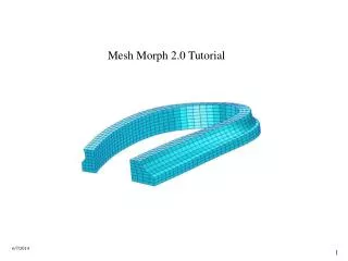
TUTORIAL 8 MESH INDEPENDENT CONNECTIONS
260 likes | 390 Vues
This tutorial guides users through the process of creating mesh-independent weld connections in MSC SOFY. It covers essential steps such as opening the MSC SOFY database, importing a Master Weld file, mapping connection groups to parts, and creating independent welds. Users will learn to navigate the interface, utilize connection group functionalities, and modify weld elements effectively. Each step includes instructions, including prompts for mouse button actions, to ensure clarity and ease of use for users of all levels.

TUTORIAL 8 MESH INDEPENDENT CONNECTIONS
E N D
Presentation Transcript
As in the other tutorials, all menu items that need to be selected will be preceded by a maroon right arrow: >User action. Mouse buttons are indicated as follows: -- 1B = First (left) button -- used for selecting items-- 2B = Second (middle) button -- used for "OK"-- 3B = Third (right) button -- used for View Manipulation & pop-up menusNormally 1B is used, unless otherwise. Table of Contents SectionPage Step1. Open MSC.Sofy Database. 3 Step2. Import Master Weld File. 4 Step3. Find Out How Conn. Groups Are Associated With Parts. 6 Step4. Create Mesh Independent Welds 9 Step5. Use Grow Mesh Command. 14 Step6 . Add Multiple Welds Along Flange. 16 Step7 . Check Connectivity Between Parts. 18 Step8 . Add New Connections. 19 Step9 . Replace And Reconnect New Part. 20 Step10. Convert From Meshless To Node-To-Node. 22 First you will be opening a model containing several panels to be welded. You will import connection locations and part information from a Master Weld File, then create mesh less weld elements. Alternate instructions for LS-DYNA users are in green text.
Step1. Open MSC.Sofy Database. e • Launch MSC.SOFY according to your local configuration . • Select NASTRAN (or LS-DYNA) mode from the entry screen. • Click the icon for ">Open SOFY DB. • In the dialog box, browse to locate the file: ...\SOFY3.0/SOFY_MASTER2/DEMOS/Tutorials_Basic/tutor08_ubody_conn.sof. • You should see on your canvas a model containing a partial underbody of a car body. • Set the View to >Left-Front and >Fill the canvas. • Note that all parts have been meshed, but not connected. • Check for weld elements by turning off all shell elements. • In Bottom Block, un-check box for >2D elements. • There are no other element types left to display. • Turn >2D elements back on by checking the box. i
Step2. Import Master Weld File. a • In Collection block, change Type to >Connection Groups. • Note there are no connection groups yet defined. • Now let's import weld locations from a Master Weld file. • But first, set the import options: • Top bar >Options >I/O Options> MWF Options>Input Options • In the dialog box, make sure the box next to "With ConnPart Names" is not checked. • This indicates that the file contains part ID numbers (for example, manufacturer's Part Numbers) rather than names. e A MWF file contains either Part names or ID numbers. When importing that file you must specify which format is used. If you're not sure, you can browse the MWF file with a text editing program, like Notepad. The second and third fields from the right will have either part names or part ID numbers. f
If any connections failed during the import process, warning messages are placed in the file"mwf.err" Failed connections, if any, are placed in single Connection Group: "FAILED CG." Step2. Import Master Weld File. (Cont’d) l i j • To import the MWF, Select >File >Import >MWF. • In the dialog box, locate the file "...\tutor08_ubody.mwf“ • Click >Open. • When the import is complete, you should see many Connection Groups now appear in the Collection Block. • Clone the collection block to view all fields: Click >Clone (left of Collection Block)>Clone Collection. • Turn off / on some Connection Groups to get a feel for how the connections are organized. • Finish by clicking >AllOn. • The model with successfully imported Spotwelds should look as shown. o
Step3. Find Out How Conn. Groups Are Associated With Parts. There are several ways to query the model to find out how parts and connection groups are associated to one another. Let's look at a couple of them: • You can identify the parts for each connection group by selecting it on the canvas. • Top bar >Conn >Attached Parts. • In Pick block > choose >Conn. Groups c b
Step3. Find Out How Conn. Groups Are Associated With Parts. (Cont’d) d • Select >connection on the canvas, as shown. • Confirm with >(2B), then you will see highlighted all the parts that are in that connection group. • In a similar way, you can display all the connection groups associated with a Part. • Go to >Part Menu>Connected Conn Groups. • Select a >part of interest from the canvas, perhaps the cross-bar (pink ) nearest the top of the screen. e h g
Step3. Find Out How Conn. Groups Are Associated With Parts. (Cont’d) i • Confirm with >2B and the associated connection groups are highlighted • Now you are ready to create mesh-independent welds for the whole model. • First make sure all Connection Groups are ON: Collection Block>click >Rst, (Reset filters) click >All On. l. Make sure entire model is displayed in the canvas by clicking on >Fill command. k
Step4. Create Mesh Independent Welds. • Please choose one of the following and proceed to the appropriate step: • For CWELD's continue with step 1.0 • For RSM welds, skip Step 1.0 and go to Step 2.0 • For ACM2 welds, go to Step 3.0 • For LS-DYNA users, create MAT100's as shown in Step 4.0 • 1.0 To create CWELD's • Conn menu (top bar) >Mesh Independent >Create CWELD from SW. • In the Pick block you are prompted to selectConnections. • Click >ALL to choose all displayable Spotweld connections. • Click >Done. a b
Any failed connections would have messages posted in the file: "c_weld.err" which you can browse in Notepad. Step4. Create Mesh Independent Welds. (Cont’d) i • After some processing time, you will see some messages in the bottom block. • Note that a new part, "CWELD PART" has been created, containing the CWELD elements. • In Collection block, change Type to >Part • Click >All On. • If you zoom in on a CWELD element, it appears as shown. Proceed to Grow Mesh command.
Step4. Create Mesh Independent Welds. (Cont’d) b a 2.0 To create RSM Welds: • Select >RSM Welds menu >Create RSM Welds. • In the Pick block you are prompted to select Connections. • Click >ALL to choose all displayed Spotweld connections. • Then click >Done. • After some processing time, you will see a completion message in the bottom block. • Note that two new parts, "CBUSH for RSM" and "WELD_PLOTELS" have been created, containing the RSM elements • To see, in Collection block, change Type to >Part >click >All On . • Also there is a new Boundary Condition set created. (In Collection block> change Type to >BC Set) • This set contains the MPC equations associated with the RSM elements. • If you zoom in on a RSM weld, it appears as shown. Proceed to Grow Mesh command. c j
Step4. Create Mesh Independent Welds. (Cont’d) b 3.0 To create ACM2 welds • Conn menu >select >Mesh Independent >Create ACM2 from SW. • In the Pick block > select >Connections. • Click >ALL to choose all displayable Spotweld connections. • Click >Done. • Enter the appropriate >Contact Factor in the pop-up, then >OK. • After some processing time, you will see some messages in the bottom block. • Note that two new parts, "acm2" and "meshless" have been created, containing the solid and RBE3 elements. • In Collection block, change Type to >Part, and click >All On. • If you zoom in on a ACM2 weld, it looks like shown. Proceed to Grow Mesh command . a i
Any failed connections would be placed in a set, "Failed spotwelds." Also any error messages are posted in the file: "mi_weld.err" which you can browse in Notepad. Step4. Create Mesh Independent Welds. (Cont’d) c 4.0 To create MAT100's: • Conn menu >Mesh Independent>Create MI (Parts). • In the Pick block you have several options to select from: >Contact: Spotweld >Contact: Tied edge to surf. >Slave: Beam parts >Slave: Beam nodes >Without Spotweld Failure >With Spotweld Failure • Now you will select Connections for creating the weld elements. • Click >ALLto choose all displayable Spotweld connections. • Thenclick >Done. • After some processing time, you will see some messages in the bottom block. • Note that several new parts, such as "Beam Welds betw P1 - P10" have been created, containing the MAT100 elements. • In Collection block, change Type to >Part, and click >All On. • There is also a new part, "Weld Display Part" that has contains display elements for all the welds. • If you zoom in on a mesh independent element, it appears as shown. a j
Step5. Use Grow Mesh Command. a Check connections using Grow Mesh command • First turn Connection Groups and BC Sets >AllOff for a cleaner display. • Now turn offall parts but one. • Select >Organize command from >Display menu, or by clicking on the icon. • In Pick block activate >Keep button, and choose entity type >Part. • Now select a >part from the canvas, for example, the right rocker inner panel (red color, part name: Pnl_Rkr_Inr_R). • Then confirm with >2B and the canvas should contain only that part, as shown. c e f
Step5. Use Grow Mesh Command. (Cont’d) g • Now click the "Grow Mesh" icon. • At first, only the connected 1D elements appear, but repeatedly clicking the icon will bring up all connected elements, one level at a time. • After several clicks, our mesh has grown as shown. • You may also find it useful to use Grow Mesh command on selected connections to check connectivity. i
Step6. Add Multiple Welds Along Flange. A convenient way to add multiple welds along a flange is as follows: • First create a line along which the welds will be placed. • Top bar >Edit >Create >Geometry >Polyline/ Spline. • If existing nodes on the mesh are available to define the curve, use "shortest path"option to quickly create the line. • Open the Extended Pick Dialog (EPD) by selecting >D on left side of Pick Block. • In EPD, choose >Shortest Path option under "Pick Node by Reference." b d e
Step6. Add Multiple Welds Along Flange. (Cont’d) f • Then pick the >start and finish points of the curve and it will be immediately created. • Now to create spotwelds along a line:- Select >Edit (top bar) >Create >Connection>Spotweld. • In Pick block, change pick entity to >Curves. • Now select the >curve from the canvas. • Confirm with >2B. • A dialog box will appear, in which you select either >Pitch (spacing between connections) OR >Number (specific number of welds along the curve). • Fill in the appropriate values, and click >OK. • The new connections will appear along the curve. • This is most useful for long flanges, etc. • You can now create the NASTRAN weld elements for these new Connections in the same way as before (refer Step4:- 1.0,2.0,3.0 For LS-DYNA, Step4 - 4.0) If it becomes necessary to replace a part, this can be easily done using the Replace Part wizard, while retaining the related connections. h m k
Step7. Check Connectivity Between Parts. Here's how you use the "Connected Parts“ command to find all parts connected to a selected part: • Use >Organize command >Keep> Parts. • From canvas, select a >part, perhaps the pink cross bar you looked at earlier (Cross_Bar_3R), then confirm with >2B. You should be left with only one part on the canvas. • To locate all parts connected to this one Part (Top Bar)>Connected Parts. • Select the >part again, followed by >2B. • Immediately, all connected parts are returned to the display. • In this case there are four parts connected through weld elements. b e
In this Pick mode you have two mouse clicks for each selection: First to select an element Second to pick a point on the element. Step8. Add New Connections. You may have noticed that there are some missing connections between this part and the floor panel. Let's add some connections. • First, designate which Conn. Group will contain the new connections. • Click with 2B on the name, in this case, >bar3_flr (ID =7), to make it the Current connection group. • Turn on all connection groups by clicking >AllOn. • Top bar >Edit >Create>Conn >Spotweld. • In Pick block, "In Curr Conn Grp" and entity type "Pt on element" should already be selected (default). • Place three spotwelds on the front flange, as shown. • Confirm with >2B and the three Spotwelds are created. h m k j
Step9. Replace And Reconnect New Part. e • In this example you'll replace the "Cross_Bar_#3L" with a revised part, which has already been meshed. • While importing the new part(s) the wizard will look for any parts with the same id's as existing parts. • First let's change the Input options to avoid renumbering of part id's during import. • Select >Options menu>I/O Options >NASTRAN Options >Input Options. • In the dialog box, Un-check the box for "Offset Part ID's“. • Top bar (select) >Modules >CAE-Wiz(ards) >Replace Parts. • In the dialog box, you are prompted to "Select a NASTRAN data deck to merge." • Navigate to the file ....\SOFY3.0/SOFY_MASTER2/DEMOS/Tutorials_Basic/tutor08_mod_crsbar3L.nas • click >Open. • When the dialog box appears asking "New part design - Process?, click >Process. • Watch for messages in the pop-up Information Panel. f k
Step9. Replace And Reconnect New Part. (Cont’d) • In the next pop-up, "Delete all duplicate parts?“>click >Delete "Reconnect the Parts?“>click>Yes m. The Wizard takes care of re-assigning all Connections to the new part. After Before
Step10.Convert From Meshless To Node-To-Node. • First make sure that all existing weld elements are defined as MSC.SOFY connections. • In our example, this is already done, but if needed you would use one of the following commands: • >Conn >Create from Loc's • >Conn >Create from Rigids / Generics • >Conn >Create from 2-noded elem's • >Conn >Mesh Independent >Create SW from ACM2 • >Conn >Mesh Independent >Create SW from RSM • Delete the existing weld elements: • Edit >Delete FEM. • In Pick block, choose entity type >Part. • Select the part >C WELD PART from the Collection block or canvas. • Click >Done to delete the part. • Turn on all Parts and Connection Groups: in Collection Block >All On. • If desired, change connection options and evaluate connections in >Options >Connection Options, as was done in Tutorial 7. • Now connect all parts with rigid elements: >Conn >CONNECT. • (or >Connect from Connection Options dialog) MSC.SOFY can quickly convert one element type to another. In this example you will convert the mesh-independent CWELD elements to node-node RBE2 type elements. h
Step10.Convert From Meshless To Node-To-Node. (Cont’d) j • Zoom in on any area of interest to check the mesh, and note that the mesh has been modified to place nodes near the connection locations. • Check element quality by activating fringes icon • Check element quality: Element >Quality >Check Quality. • Modify any quality criteria and activate or de-activate any of the quality checks, as desired. • Enhance the quality by choosing Element >Quality >Enhance Quality • Select all displayed elements by clicking >DISP in Pick block. • To QUIT: Top-Bar >File >Quit. Don't Save. o k
Congratulations, You have just completed Tutorial 8 !!!