Understanding Audio Mixers: The Heart of Sound Control Systems
260 likes | 429 Vues
This guide delves into the essential role of audio mixers in sound systems, highlighting their designations, inputs, outputs, and signal processing capabilities. Audio mixers, also known as mixing consoles or sound boards, serve as the main tool for operators, enabling the selection and manipulation of audio signals from various sources, such as microphones and playback devices. We explore fundamental concepts like signal routing, pre-amplification, equalization, and auxiliary sends, all critical to effective sound management in various settings, from recording studios to live performances.

Understanding Audio Mixers: The Heart of Sound Control Systems
E N D
Presentation Transcript
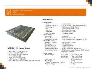
Mixing Consoles Designations Inputs Outputs Signal processing
Sound Control Mixer - Heart of the Audio System • Mixer - Heart of the Sound system • Sound Board, Audio Console, Mixing desk • Main tool of the operator (Board Operator) • Basic Purpose - Controls • What is it - Selects audio signals from various sources • Devices are connected to input channels • Microphones • Output channels of CD players, MD players, DAT players, computers • How Loud will it be - Controls signal level (volume) • Where is it going - Sends audio to various locations • Devices are connected to outputs • Power amplifiers • Input channels of MD players, DAT players, Computers
Sound Control Mixer - Heart of the System • Mixer Nomenclature (Functional Description) • 8x2 = 8 inputs and 2 outputs • 16x4 = 16 inputs and 4 outputs • 16x4x2 = 16 inputs, 4 group of sub outs, 2 main outs. Can be used as: • 16 ins mixed down to 4 sub mixes, mixed down to 2 output channels (recording studio or concert presentation) utilization • 24x6 (Theatre type utilization) • 16x4x2x1 – adds a mono output • Also can be referred simply by the number of input channels ex. 8, 16, 24, 48 etc…
Mixer Amp Upstage L/R MD 1 MD 2 Amp Cass Cluster Computer Amp Radio Record Player Cue Control Audio System – Sources, Control, Destinations Equipment System is the Primary Tool of Modern Theatre Sound Design: • Block Diagram - Foreigner Setup 1 - 2 L/R Mono 3 Group/ Outs 1-2 3-4 5-6 7-8 Input Channels
Input Buss • This is the section where audio signals from microphones and/or playback equipment enters the mixer • This is the area where impedance matching and Balanced / Un-balanced lines must be carefully watched • The input buss typically starts at the rear of the console with either XLR or ¼” TRS connectors
Input Buss Rear view of a Mackie t24
Input Buss • The front side of the console will differ from manufacturer to manufacturer but they will have most of the same components • The input channel will usually be arranged to follow the virtual signal path
Input Buss • Pre-amplifier • Pre-amp, trim, trim pot, gain • Used to bring a microphone level signal up to line level for easy manipulation within the mixer • Also used to adjust the line level inputs from other sources • Pad or Attenuator • A switch which will lower an inputs level by a set amount • Usually used in an input device is too “hot” or much too high a level
Close up of Pre-amp section Input channel # Pad / low end roll off Gain adjust
Equalization section • Onboard equalization control will vary greatly • Simple “tone” control • Simply varies the balance between high and low frequencies • Treble and Base • Boost or attenuate high frequencies (treble) or low frequencies (base) • Only adjusts a preset range of frequencies • Hi – Mid – Lo • A fancier version of treble and base control • 5 band EQ • Able to boost of attenuate 5 different ranges of frequencies • Parametric EQ • Able to select which frequency range to control and then boost or cut it
Equalization section High freq. control High-mid with selectable frequency range Low-mid with selectable frequency range Low frequency control
Auxiliary Sends • Next in line comes a number of Aux sends • Typically 4 to 8 individual busses • Some or all will be pre or post fader selectable • Pre-fader – the signal strength (volume) coming from the aux send channel will be independent on the position of the channel fader • Post-fader – the signal strength coming from the aux send will be dependent on the position of the channel fader • Often labeled as PFL (Pre-Fade Listen) • Often used to send signals to other devices • External effect processor • Reverb or echo • Monitor amp/speakers for performers
Auxiliary Sends Note the pre-fade switch 8 individual aux send channels
Signal Routing • Each input channel will be assignable to one or more output channels • Very often one selector button will assign the input to two separate outputs • 1-2 or 3-4 for example • The Pan Pot (Panoramic Potentiometer) adjusts the level of signal going to each of the pairs • Example: With the pan pot centered and 1-2 selected, the entire signal is sent to outputs 1 and 2 equally. If you turn the pot to the left, more signal will be sent to output 1 than output 2 • This is usually to be avoided for theatrical use • Look for single output selection control if possible • PFL – Pre-fade Listen. Sometimes called “solo” • Usually available to send the signal to a studio monitor or headphones to allow operator to listen to channel without having to send it into the house • Channel Mute – turns the channel off. Useful when using wireless mics
Signal Routing Pan Pot Output selection Mute Note: PFL not available on this model
Other input controls • Phantom power • A 48v DC power supply applied to the mic input lines • Used to power condenser mics (to be discussed later) • Phase reverse • Inverts the signal coming to the inputs • Used if pins 2 and 3 on a mic cable are reversed for example • Ground lift • Removes the ground connection at the console from the input cable • Used to help eliminate ground-loop noise • To be discussed during troubleshooting
Output Section • This is the area where audio signals will leave the mixer, heading toward • Effects processors • EQs, delay units, reverb units, recording devices • Power amplifiers and eventually loudspeakers • Output plugs will typically be • Balanced XLR line level • Balanced TRS line level • Unbalanced ¼” phone plug line level • Unbalanced RCA plug line level
Output Section Left, Right and Main outputs Sub or group outputs Auxiliary outputs
Output Section • Sub-group output faders • Sometimes called groups, subs or submasters • Act as a master fader control for any inputs assigned to it • Typically these are cabled to power amplifiers • Main outputs • Sometimes called Left-Right, Stereo or Mix • Essentially two additional outputs, where the manufacturer has taken a guess as to what the end user will use them for • Sub groups can usually be combined and selectively assigned to the main output • Master output • Sometimes called Mono • The main outputs can be combined together and controlled from one master fader
Aux-Output Section Aux out mute switch Aux out gain control After fader listen
“Flying Faders” • Automated mixers are becoming more and more common • Started simply to record levels in recording studios • Often had 60 or more inputs levels to write down and could have many many setups. • Flying faders would remember where the faders were set and you could restore to any setting with the push of a button
“Flying Faders” • Today mixers are capable of remembering output selections, EQ settings, pan settings etc. • For live mixing it is REQUIRED to still have actual faders which an operator can move • Performers will never do the exact thing every night • The board operator must be able to easily make adjustments to levels on the fly
For Next Class • Read