
Multiple Access: Solving Networking Challenges
E N D
Presentation Transcript
Multiple Access An Engineering Approach to Computer Networking
What is it all about? • Consider an audioconference where • if one person speaks, all can hear • if more than one person speaks at the same time, both voices are garbled • How should participants coordinate actions so that • the number of messages exchanged per second is maximized • time spent waiting for a chance to speak is minimized • This is the multiple access problem
Some simple solutions • Use a moderator • a speaker must wait for moderator to call on him or her, even if no one else wants to speak • what if the moderator’s connection breaks? • Distributed solution • speak if no one else is speaking • but if two speakers are waiting for a third to finish, guarantee collision • Designing good schemes is surprisingly hard!
Outline • Contexts for the problem • Choices and constraints • Performance metrics • Base technologies • Centralized schemes • Distributed schemes
Contexts for the multiple access problem • Broadcast transmission medium • message from any transmitter is received by all receivers • Colliding messages are garbled • Goal • maximize message throughput • minimize mean waiting time • Shows up in five main contexts
Solving the problem • First, choose a base technology • to isolate traffic from different stations • can be in time domain or frequency domain • Then, choose how to allocate a limited number of transmission resources to a larger set of contending users
Outline • Contexts for the problem • Choices and constraints • Performance metrics • Base technologies • Centralized schemes • Distributed schemes
Choices • Centralized vs. distributed design • is there a moderator or not? • in a centralized solution one of the stations is a master and the others are slaves • master->slave = downlink • slave->master = uplink • in a distributed solution, all stations are peers • Circuit-mode vs. packet-mode • do stations send steady streams or bursts of packets? • with streams, doesn’t make sense to contend for every packet • allocate resources to streams • with packets, makes sense to contend for every packet to avoid wasting bandwidth
Constraints • Spectrum scarcity • radio spectrum is hard to come by • only a few frequencies available for long-distance communication • multiple access schemes must be careful not to waste bandwidth • Radio link properties • radio links are error prone • fading • multipath interference • hidden terminals • transmitter heard only by a subset of receivers • capture • on collision, station with higher power overpowers the other • lower powered station may never get a chance to be heard
The parameter ‘a’ • The number of packets sent by a source before the farthest station receives the first bit
Outline • Contexts for the problem • Choices and constraints • Performance metrics • Base technologies • Centralized schemes • Distributed schemes
Performance metrics • Normalized throughput • fraction of link capacity used to carry non-retransmitted packets • example • with no collisions, 1000 packets/sec • with a particular scheme and workload, 250 packets/sec • => goodput = 0.25 • Mean delay • amount of time a station has to wait before it successfully transmits a packet • depends on the load and the characteristics of the medium
Performance metrics • Stability • with heavy load, is all the time spent on resolving contentions? • => unstable • with a stable algorithm, throughput does not decrease with offered load • if infinite number of uncontrolled stations share a link, then instability is guaranteed • but if sources reduce load when overload is detected, can achieve stability • Fairness • no single definition • ‘no-starvation’: source eventually gets a chance to send • max-min fair share: will study later
Outline • Contexts for the problem • Choices and constraints • Performance metrics • Base technologies • Centralized schemes • Distributed schemes
Base technologies • Isolates data from different sources • Three basic choices • Frequency division multiple access (FDMA) • Time division multiple access (TDMA) • Code division multiple access (CDMA)
FDMA • Simplest • Best suited for analog links • Each station has its own frequency band, separated by guard bands • Receivers tune to the right frequency • Number of frequencies is limited • reduce transmitter power; reuse frequencies in non-adjacent cells • example: voice channel = 30 KHz • 833 channels in 25 MHz band • with hexagonal cells, partition into 118 channels each • but with N cells in a city, can get 118N calls => win if N > 7
TDMA • All stations transmit data on same frequency, but at different times • Needs time synchronization • Pros • users can be given different amounts of bandwidth • mobiles can use idle times to determine best base station • can switch off power when not transmitting • Cons • synchronization overhead • greater problems with multipath interference on wireless links
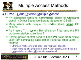
CDMA • Users separated both by time and frequency • Send at a different frequency at each time slot (frequency hopping) • Or, convert a single bit to a code (direct sequence) • receiver can decipher bit by inverse process • Pros • hard to spy • immune from narrowband noise • no need for all stations to synchronize • no hard limit on capacity of a cell • all cells can use all frequencies
CDMA • Cons • implementation complexity • need for power control • to avoid capture • need for a large contiguous frequency band (for direct sequence) • problems installing in the field
FDD and TDD • Two ways of converting a wireless medium to a duplex channel • In Frequency Division Duplex, uplink and downlink use different frequencies • In Time Division Duplex, uplink and downlink use different time slots • Can combine with FDMA/TDMA • Examples • TDD/FDMA in second-generation cordless phones • FDD/TDMA/FDMA in digital cellular phones
Outline • Contexts for the problem • Choices and constraints • Performance metrics • Base technologies • Centralized schemes • Distributed schemes
Centralized access schemes • One station is master, and the other are slaves • slave can transmit only when master allows • Natural fit in some situations • wireless LAN, where base station is the only station that can see everyone • cellular telephony, where base station is the only one capable of high transmit power
Centralized access schemes • Pros • simple • master provides single point of coordination • Cons • master is a single point of failure • need a re-election protocol • master is involved in every single transfer => added delay
Circuit mode • When station wants to transmit, it sends a message to master using packet mode • Master allocates transmission resources to slave • Slave uses the resources until it is done • No contention during data transfer • Used primarily in cellular phone systems • EAMPS: FDMA • GSM/IS-54: TDMA • IS-95: CDMA
Polling and probing • Centralized packet-mode multiple access schemes • Polling • master asks each station in turn if it wants to send (roll-call polling) • inefficient if only a few stations are active, overhead for polling messages is high, or system has many terminals • Probing • stations are numbered with consecutive logical addresses • assume station can listen both to its own address and to a set of multicast addresses • master does a binary search to locate next active station
Reservation-based schemes • When ‘a’ is large, can’t use a distributed scheme for packet mode (too many collisions) • mainly for satellite links • Instead master coordinates access to link using reservations • Some time slots devoted to reservation messages • can be smaller than data slots => minislots • Stations contend for a minislot (or own one) • Master decides winners and grants them access to link • Packet collisions are only for minislots, so overhead on contention is reduced
Outline • Contexts for the problem • Choices and constraints • Performance metrics • Base technologies • Centralized schemes • Distributed schemes
Distributed schemes • Compared to a centralized scheme • more reliable • have lower message delays • often allow higher network utilization • but are more complicated • Almost all distributed schemes are packet mode (why?)
Decentralized polling • Just like centralized polling, except there is no master • Each station is assigned a slot that it uses • if nothing to send, slot is wasted • Also, all stations must share a time base
Decentralized probing • Also called tree based multiple access • All stations in left subtree of root place packet on medium • If a collision, root <- root ->left_son, and try again • On success, everyone in root->right_son places a packet etc. • (If two nodes with successive logical addresses have a packet to send, how many collisions will it take for one of them to win access?) • Works poorly with many active stations, or when all active stations are in the same subtree
Carrier Sense Multiple Access (CSMA) • A fundamental advance: check whether the medium is active before sending a packet (i.e carrier sensing) • Unlike polling/probing a node with something to send doesn’t have to wait for a master, or for its turn in a schedule • If medium idle, then can send • If collision happens, detect and resolve • Works when ‘a’ is small
Simplest CSMA scheme • Send a packet as soon as medium becomes idle • If, on sensing busy, wait for idle -> persistent • If, on sensing busy, set a timer and try later -> non-persistent • Problem with persistent: two stations waiting to speak will collide
How to solve the collision problem • Two solutions • p-persistent: on idle, transmit with probability p: • hard to choose p • if p small, then wasted time • if p large, more collisions • exponential backoff • on collision, choose timeout randomly from doubled range • backoff range adapts to number of contending stations • no need to choose p • need to detect collisions: collision detect circuit => CSMA/CD
Ethernet • The most widely used LAN • Standard is called IEEE 802.3 • Uses CSMA/CD with exponential backoff • Also, on collision, place a jam signal on wire, so that all stations are aware of collision and can increment timeout range • ‘a’ small =>time wasted in collision is around 50 microseconds • Ethernet requires packet to be long enough that a collision is detected before packet transmission completes (a <= 1) • packet should be at least 64 bytes long for longest allowed segment • Max packet size is 1500 bytes • prevents hogging by a single station
More on Ethernet • First version ran at 3 Mbps and used ‘thick’ coax • These days, runs at 10 Mbps, and uses ‘thin’ coax, or twisted pair (Category 3 and Category 5) • Ethernet types are coded as <Speed><Baseband or broadband><physical medium> • Speed = 3, 10, 100, 1000, 10000 Mbps • Baseband = within building, broadband = on cable TV • Physical medium: • “2” is cheap 50 Ohm cable, upto 185 meters • “T” is unshielded twisted pair (also used for telephone wiring) • “36” is 75 Ohm cable TV cable, upto 3600 meters
developments • Switched Ethernet • each station is connected to switch by a separate UTP wire • line card of switch has a buffer to hold incoming packets • fast backplane switches packet from one line card to others • simultaneously arriving packets do not collide (until buffers overflow) • higher intrinsic capacity than 10BaseT (and more expensive)
Fast Ethernet variants • Fast Ethernet (IEEE 802.3u) • same as 10BaseT, except that line speed is 100 Mbps • spans only 205 m • big winner • most current cards support both 10 and 100 Mbps cards (10/100 cards) for about $80 • 100VG Anylan (IEEE 802.12) • station makes explicit service requests to master • master schedules requests, eliminating collisions • not a success in the market • Gigabit Ethernet & 10GigE • aims to continue the trend • still undefined, but first implementation will be based on fiber links
Evaluating Ethernet • Pros • easy to setup • requires no configuration • robust to noise • Problems • at heavy loads, users see large delays because of backoff • nondeterministic service • doesn’t support priorities • big overhead on small packets • But, very successful because • problems only at high load • can segment LANs to reduce load
CSMA/CA • Used in wireless LANs • Can’t detect collision because transmitter overwhelms colocated receiver - might change in future… • So Collision Avoidance (CA) not Detection (CD) • So, need explicit acks • But this makes collisions more expensive • => try to reduce number of collisions
CSMA/CA algorithm • First check if medium is busy • If so, wait for medium to become idle • Wait for interframe spacing • Set a contention timer to an interval randomly chosen in the range [1, CW] • On timeout, send packet and wait for ack • If no ack, assume packet is lost • try again, after doubling CW • If another station transmits while counting down, freeze CW and unfreeze when packet completes transmission • (Why does this scheme reduce collisions compared to CSMA/CD?)
Dealing with hidden terminals • CSMA/CA works when every station can receive transmissions from every other station • Not always true • Hidden terminal • some stations in an area cannot hear transmissions from others, though base can hear both • Exposed terminal • some (but not all) stations can hear transmissions from stations not in the local area
Dealing with hidden and exposed terminals • In both cases, CSMA/CA doesn’t work • with hidden terminal, collision because carrier not detected • with exposed terminal, idle station because carrier incorrectly detected • Two solutions • Busy Tone Multiple Access (BTMA) • uses a separate “busy-tone” channel • when station is receiving a message, it places a tone on this channel • everyone who might want to talk to a station knows that it is busy • even if they cannot hear transmission that that station hears • this avoids both problems (why?)
Multiple Access Collision Avoidance • BTMA requires us to split frequency band • more complex receivers (need two tuners) • Separate bands may have different propagation characteristics • scheme fails! • Instead, use a single frequency band, but use explicit messages to tell others that receiver is busy • In MACA, before sending data, send a Request to Sent (RTS) to intended receiver • Station, if idle, sends Clear to Send (CTS) • Sender then sends data • If station overhears RTS, it waits for other transmission to end • (why does this work?)
Token passing • In distributed polling, every station has to wait for its turn • Time wasted because idle stations are still given a slot • What if we can quickly skip past idle stations? • This is the key idea of token ring • Special packet called ‘token’ gives station the right to transmit data • When done, it passes token to ‘next’ station • => stations form a logical ring • No station will starve
Logical rings • Can be on a non-ring physical topology
Ring operation • During normal operation, copy packets from input buffer to output • If packet is a token, check if packets ready to send • If not, forward token • If so, delete token, and send packets • Receiver copies packet and sets ‘ack’ flag • Sender removes packet and deletes it • When done, reinserts token • If ring idle and no token for a long time, regenerate token
Single and double rings • With a single ring, a single failure of a link or station breaks the network => fragile • With a double ring, on a failure, go into wrap mode • Used in FDDI