Download
1 / 56
560 likes | 583 Vues
Learn about Geiger-Mueller tubes introduced by Geiger and Mueller in 1928, their operation, use in detecting radiation, and evolution into proportional counters for medical and scientific applications. Discover the technology behind generating high voltage for precise measurements and improving position resolution.

E N D
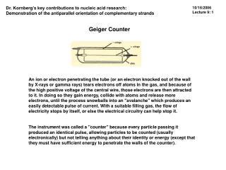
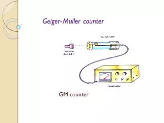
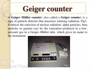
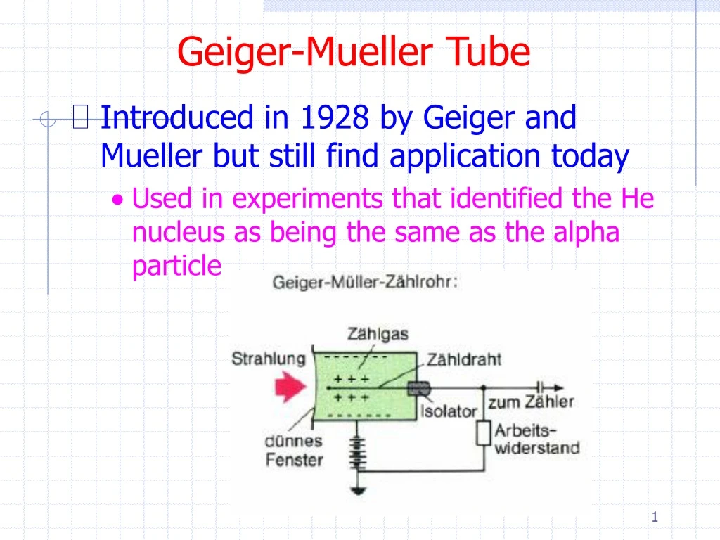
Geiger-Mueller Tube • Introduced in 1928 by Geiger and Mueller but still find application today • Used in experiments that identified the He nucleus as being the same as the alpha particle
Geiger-Mueller Tube • Operation • Increasing the high voltage in a proportional tube will increase the gain • The avalanches increase not only the number of electrons and ions but also the number of excited gas molecules • These (large number of) photons can initiate secondary avalanches some distance away from the initial avalanche by photoelectric absorption in the gas or cathode • Eventually these secondary avalanches envelop the entire length of the anode wire • Space charge buildup from the slow moving ions reduce the effective electric field around the anode and eventually terminate the chain reaction
Geiger-Mueller Tube • Gas • The main component is often argon or neon • However when the large number of these noble ions arrive at the cathode and are neutralized, the released energy can cause additional free electrons to be liberated from the cathode • This gives rise to multiple pulsing (avalanches) in the G-M tube
Geiger-Mueller Tube • Gas • Multiple pulsing can be quenched by the addition of a small amount of chlorine (Cl2) or bromine (Br2) (the quench gas) • As we mentioned earlier, collisions between ions and different species of gas molecules tend to transfer the charge to the one with the lowest ionization potential • When the halogen ions are neutralized at the cathode, disassociation can occur rather than extraction of a free electron
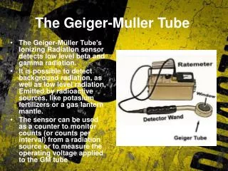
Geiger-Mueller Tube • Use • Geiger tubes are often used as survey meters to detect or monitor radiation • They are rarely used as dosimeters but there are some applications • Survey meters generally have units of CPM or mR/hr but beware/check the calibration information • If calibrated, the survey meter is calibrated to some fixed gamma ray energy • For other gamma ray energies one must account for differences in efficiency
Geiger Tube • How is 900V generated from 1.5V batteries? • Diodes are nonlinear circuit elements that only conduct current in one direction
Geiger Tube • Voltage doubler
Geiger Tube • On one half-cycle, D1 conducts and charges C1 to V • On the other half-cycle D2 conducts and charges C2 to 2V • A long string of half-wave doublers is known as a Cockcroft-Walton multiplier
Geiger Tube • This can be extended to an n multiplier
Proportional Counters • Many different types of gas detectors have evolved from the proportional counter
Proportional Counters • Most of these variants were developed to improve position resolution, rate capability, and/or cost • MWPC (multi-wire proportional tube) • CSC (cathode strip chamber) • Drift chamber (e.g. MDT) • Micromegas (micromesh gaseous detector) • RPC (resistive plate chamber) • Nearly every application has made some attempt to transfer to medical applications
Momentum Measurement • Let v, p be perpendicular to B
Momentum Resolution • The sagitta s can be determined by at least 3 position measurements • This is where the position resolution of the proportional chambers comes in
Solenoid Large homogeneous field Weak return field in return yoke Dead material in beam Toroid Field always perpendicular to p (ideal) Large volume Non-uniform field Complex Magnets
ATLAS CMS Magnets
Momentum Resolution • ATLAS muon momentum resolution
Multiwire Proportional Chambers (MWPC’s) • Nobel prize to Charpak in 1992 • Simple idea to extend the proportional tube • Effectively spawned the era of precision high energy physics experiments
MWPC’s • You might expect that because of the large C between the wires, a signal induced on one wire would be propagated to its neighbors • Charpak observed that a positive signal would be induced on all surrounding electrodes including the neighbor wires (from the positive ions moving away)
MWPC’s • Typical parameters • Anode spacing – 1-2 mm • Anode – cathode spacing – 8 mm • Anode diameter – 25 mm • Anode material – gold plated tungsten • Cathode material – Aluminized mylar or Cu-Be wire • Typical gain - 105
Cathode Strip Chambers (CSC) • The negative charge induced on the anode induces positive charge on the cathodes • This provides a second detectable signal • If the surface charge density is sampled by separate cathode electrodes then the location of the avalanche can be determined • If the cathode pulse heights are well measured the position resolution can be precisely determined (~100μm vs 600μm for 2mm/√12)
Cathode Signal • Consider the geometry • The cathode charge distribution is given by • Where λ = x/d and Ki are geometry dependent constants
Cathode Signal • The shape is quasi-Lorentzian with a FWHM ~ 1.5 d, where d is the anode-cathode spacing
Cathode Signal • In order to reduce the number of readout channels one can use capacitive coupling between strips • Strip pitch is one-half or one-third • Readout pitch stays the same
ATLAS CSC’s • Some numbers • 16 four-layer CSC’s per side • Both r (precision) and f (transverse) position is measured for each layer • Each CSC has 4 x 192 precision strips • Each CSC has 4 x 48 transverse strips • 32,000 channels total
Drift Chambers • Another variation on the MWPC is the drift chamber
Drift Chambers • Advantages • Better position resolution • Smaller number of channels • Disadvantages • More difficult to construct • Need time measurement • The position resolution of drift chambers is limited by diffusion, primary ionization statistics, path fluctuations, and electronics • Many different geometries are possible
Drift Chambers • Planar chambers
Drift Chambers • CDF central tracker
ATLAS MDT’s • Some numbers • ~1200 drift chambers with ~400000 drift tubes • Covers ~5500 m2 • Optical monitoring of relative chamber positions to ~ 30mm • Ar:CO2 (93:7) pressurized to 3 bar • Track position resolution ~ 40mm
Micromegas • Principle of operation • Bulk micromegas use photolithographic techniques to produce narrow anodes and precise micromesh – anode spacing
Resistive Plate Chambers (RPC’s) • Principle of operation • Very high electric field (few kV/mm) induces avalanches or streamers in the gap • High resistivity material localizes the avalanche • Signal is induced on the readout electrodes
+++++++++++++++ _ _ _ _ _ _ _ _ _ _ _ Before +++ +++++ _ _ _ _ _ _ _ RPC’s • Avalanche mode • Like a proportional chamber • Streamer mode • Small “spark” • Excellent time resolution • 1-2 ns • In both cases charge must recover to re-establish E field after avalanche or streamer After
Bakelite Plates X readout strips Foam Gas HV Grounded planes Y readout strips PET spacers Graphite electrodes ATLAS RPC’s 2mm gas gap 8.9kV operating voltage