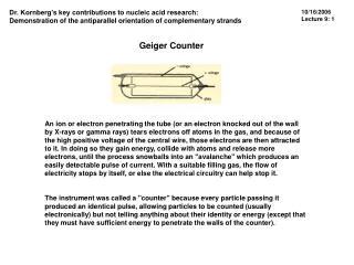
Geiger Counters
Geiger Counters. As the voltage increases in a gas detector the ions collected increases. The proportional region ends. Streamer mode Geiger mode Continuous discharge. Higher Voltage. Continuous discharge is due to the breakdown of gas into a plasma. Each gas has a threshold


Geiger Counters
E N D
Presentation Transcript
As the voltage increases in a gas detector the ions collected increases. The proportional region ends. Streamer mode Geiger mode Continuous discharge Higher Voltage
Continuous discharge is due to the breakdown of gas into a plasma. Each gas has a threshold Example: neon lamps Discharge is bad for detectors. Individual signals lost The fixed discharge threshold can be used to regulate voltage. Continuous Discharge NE-38: typical breakdown voltage 135 VDC
In proportional mode a single ion pair results in an avalanche. With higher fields electrons in the avalanche cause x-rays that start new avalanches. The process stops when sufficient positive ions quench the avalanches. Ions slowly drift to cathode Multiple Avalanches
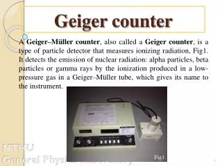
Geiger-Müller Region • In the Geiger-Müller (GM) region of operation there is a maximum amount of electrons produced in the avalanche. • Ion pair count is independent of initial ionization. • Plateau over range of voltage • The electrons are collected quickly • Less than 1 ms • Quenching gas is needed to suppress the later pulse from positive ions.
Geiger Tube • Most Geiger tubes use a cylindrical geometry. • Grounded outer cathode • High voltage anode • There is usually a thin window to allow particle to enter without loss. • The output is either from case or capacitively coupled. + output C - R V
Typical Problem In a Geiger tube with 1 kV between electrodes, a 0.5 MeV b particle produces a pulse that fully charges a 5 pF capacitor. What is the energy amplification? How many electrons are in the avalanche? Answer The energy in the capacitor is (1/2)CV2 = 2.5 x 10⁻⁶ J. 0.5 MeV = 8 x 10-14 J Gain is 3 x 10⁷ The charge Q = CV Q = 5 x 10⁻⁹ C A 5 pF capacitor Geiger Amplifier
Dead Time • The avalanche in the GM tube and pulse readout take a fixed time. • Ions need to become neutral • Dead time between pulses • At right the counter has a 90 ms dead time. • Fails near 10 kcount/s http://www.imagesco.com/articles/geiger
A single transformer could convert 120 V AC into a high voltage AC. Rectify to get DC Voltage doublers and switching circuits can pump charge into capacitors. This circuit produces DC output at 2 times the zero-to-peak input AC. Can be extended in series to higher multiples. Making High Voltage
Portable HV www.techlib.com
Portable Geiger counters often make audible clicks or beeps when an avalanche occurs. Convert pulse to greater duration Buffer signal digitally Drive inverter oscillator and speaker Pulse Beeper +9 V Geiger tube input 470 KW 10 MW 4700 pF 1 MW 220 pF ground 1 MW
GM Kits http://www.imagesco.com/articles/geiger
The 4049 Hex Inverting Buffer is set up as a square wave generator. The power MOSFET IRF830 switches the current on and off to the primary windings of the mini step-up transformer. The output of the mini step-up transformer is fed to a voltage doubler consisting of two high voltage diodes D2 and D3 and two high voltage capacitors C4 and C5. The high voltage output from this stage is regulated to 500 volts needed for our GM tube by three zener diodes stacked one on top of the other (D4, D5 and D6). Diodes D5 and D6 are 200V zener diodes and diode D4 is a 100-Volt zener. Together (200 + 200 + 100 = 500), they equal 500 volts. Five hundred volts is the optimum operating voltage for our GM Tube. The 500-volt regulated output is fed to the anode of the GM tube through a current limiting 10 mega-ohm resistor R4. The 10 mega-ohm resistor limits the current through the GM tube and helps quench the avalanched ionization when a radioactive particle is detected. The cathode of the tube is connected to a 470K (R5) resistor. The voltage pulse across R5 generated by the detection of radiation, feeds to the base of a 2N3904 NPN transistor, through a 1-uF capacitor (C6). The NPN transistor clamps the output pulse from the GM tube to Vcc and feeds it to an inverting gate on the 4049. The inverted pulse signal from the gate is a trigger to the 555 Timer. The timer is set up in monostable mode that stretches out the pulse received on its trigger. The output pulse from the timer flashes the LED and outputs an audible click to the speaker via pin 3. Circuit Description
There is a transition region between proportional and GM. Extra avalanches occur Localized compared to GM Devices in this region are limited streamer or self-quenched streamer chambers. Limited Proportional Mode
A popular application of limited streamer is the Iarocci tube. Array of rectangular tubes One conducting cathode surface Equivalent to multiwire proportional chamber Iarocci tubes can be operated in either limited streamer or proportional mode. Limited streamer mode gives greater signal strength. Proportional mode gives greater spatial precision. Iarocci Tubes
Equipotential lines in an Iarocci tube are very similar to proportional tubes near the anode. Conducting plane is resistive. Graphite coat Equipotentials
Typical LST is a multiwire unit (BaBar). Silver-plated wire 100 mm in diameter 8 wire cells per unit Quenching gas mixture Ar(3%)+Isobutane(8%)+C02(89%) Resistive layer of graphite, with resistivity between 0.2 and 1 MW/square Operates at 4.7 kV; plateaus 200 V wide Wire signals of the order of 150/200 mV Pulse 50 ns, sometimes an afterpulse Average charge per pulse of 300 pC Limited Streamer Tubes
Iarocci tubes used in tracking are arranged in layers. Hits in cells are fit to a track. Timing converted to distance from wire Fit resolves left-right ambiguity Tracking Detector