Download
1 / 18
190 likes | 257 Vues
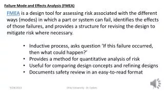
Learn about significant characteristics, special process characteristics, current controls, and effects in Failure Modes and Effects Analysis (FMEA) to ensure product quality and customer satisfaction.

E N D
Characteristics Significant Characteristics Significant Characteristics are Special Characteristics defined by Ford Motor Company as characteristics that significantly affect customer satisfaction and require quality planning to ensure acceptable levels of capability. Special Process Characteristics Special Process Characteristics are process characteristics for which variation must be controlled to some target value to ensure that variation in a Special Product Characteristic is maintained to its target value during manufacturing and assembly. Special Product Characteristics Special Product Characteristics are product characteristics for which reasonably anticipated variation could significantly affect a product’s safety or compliance with governmental standards or regulations, or is likely to significantly affect customer satisfaction with a product.
Current Controls Design and Process controls are grouped according to their purpose. Type (1) These controls prevent the Cause or Failure Mode from occurring, or reduce their rate of occurrence. Type (2) These controls detect the Cause of the Failure Mode and lead to corrective action. Type (3) These Controls detect the Failure Mode before the product reaches the customer. The customer could be the next operation, subsequent operations, or the end user. The distinction between controls that prevent failure (Type 1) and controls that detect failure (Types 2 and 3) is important. Type 1 controls reduce the likelihood that a Cause or Failure Mode will occur, and therefore affect Occurrence ratings.Type 2 and Type 3 Controls detect Causes and Failure Modes respectively, and therefore affect Detection ratings.
In the analysis of the penlight bulb, a different Function and Failure Mode(s) must be considered. The penlight bulb is intended to provide light of specific intensity when the device is activated during its expected lifetime. This is one of its Functions, or intended purposes. • A dim bulb is a failure to provide the specified intensity of light and is therefore a Failure Mode of the penlight bulb. • This example illustrates that Causes, Effects, and Failure Modes can change depending on the Function being analyzed. Functions change depending on the object of the analysis, either product or process. Therefore, an early, important step in an FMEA is to clearly define the scope: the component, system, or process that is to be analyzed.
Effects • After Functions and Failure Modes have been established, the next step in the FMEA process is to identify potential downstream consequences when the Failure Mode occurs. This should be a team brainstorming activity. After consequences have been identified, they must be fit into the FMEA model as Effects. It is assumed that Failure Mode Effects always occur when the Failure Mode occurs; there is no representation for the likelihood that a Failure Mode will result in an Effect. The Procedure for Potential Consequences is applied to account for unlikely or remote consequences. The Procedure explicitly associates Effects with the circumstances under which they occur through the identification of additional Failure Modes. • The Procedure for Potential Consequences: • Begin with a Failure Mode and a list of all its potential consequences. • Separate the consequences that can be assumed to result whenever the Failure Mode occurs. Identify these as Effects of Failure1.
Effects • Write additional Failure Modes for the remaining consequences (consequences which could result when Failure 1 occurs, depending on the circumstances under which Failure 1 occurred). • The new Failure Modes imply that unlikely consequences will result by including the circumstances under which they occur. • Separate the consequences that can be assumed to result whenever the additional Failure Modes and their special circumstances occur. Identify these consequences as Effects of the additional Failure Modes. • Consider this example, which illustrates the Procedure for Potential Consequences. During the Effects brainstorm, the team may tend to identify very severe consequences and the unlikely circumstances under which they occur. When analyzing the penlight bulb, a team member may observe that the bulb could prematurely burn out when being used as a flashlight, the resulting darkness causing the user to trip, fall, and be injured. Another member may observe that atmospheric pressure variation could cause the bulb to explode while being used for an eye examination, resulting in injury.
Effects • But rather than write a new Failure Mode for every bizarre situation recorded by the team, the events should be grouped into a broad Effect category, such as "injury or death". Ultimately, Effects are categorized into one of ten groups, according to Severity. It is advantageous to write Failure Modes that encompass all the Effects in a Severity grouping, such as "Fails to provide 3 ± .5 candela of light under critical conditions". All product failures that lead to injury or death are automatically included; there is no need to attempt to identify all the circumstances under which injury or death could result. The tradeoff for this convenience is that the likelihood of failure under any critical situation must be factored into the Occurrence rating. • Now that unlikely consequences of injury or death are represented by their own Failure Mode, the Effects will be analyzed separately, independent of the original Failure Mode "Fails to provide 3 ± .5 candela of light when on." The original Failure Mode should be modified to read: "Fails to provide 3 ± .5 candela of light under nominal conditions", which implies that Effects may be more severe under different circumstances. The Procedure for Potential Consequences is used in combination with a modified definition of Occurrence to represent Effects that do not always result when the Cause of failure occurs. The Procedure for Potential Consequences and Occurrence re-definition are presented as an improvement over Cause-Effect relationships in existing FMEA models.
Causes • After Effects and Severity have been addressed, the next step is to identify Causes of Failure Modes. This is another team activity. Identification should start with Failure Modes that have the most severe Effects. In a design FMEA, design deficiencies that result in a Failure Mode are Causes of failure. Design deficiencies that induce a manufacturing or assembly error are also included in design FMEAs as Causes. The design FMEAassumes that manufacturing and assembly specifications are met, and only seeks to identify failures resulting from product design. • In a process FMEA, Causes are specific errors described in terms of something that can be corrected or controlled. The process FMEAassumes that the product is adequately engineered, and will not fail because of a design deficiency. This does not imply that all inputs to the process meet engineering specifications. Variation in purchased parts and material used in the process should be considered in the process FMEA.
Occurance • Causes are rated in terms of Occurrence. Occurrence is the likelihood that that a particular Cause will occur and result in the Failure Mode during the intended life and use of the product. This definition is distinctly different from the definition published by the AIAG. In the AIAG FMEA model, Occurrence is simply the likelihood that a Cause or mechanism of failure will occur. It is assumed that the failure itself could occur, but not necessarily. Since Occurrence is defined only as the likelihood the Cause will occur, there is no way of quantifying the likelihood that the Failure Mode and subsequent Effects will result. • The Occurrence definition, used in combination with the Procedure for Potential Consequences, accounts for the fact that Causes do not always lead to Failure Modes and subsequent Effects. When applicable, the Procedure for Potential Consequences isolates severe Effects from the group by definition of a new Failure Mode with special circumstances. The Causes of the new Failure Mode are assigned Occurrence values. The new Occurrence values represent the remote likelihood that the customer will experience the Effect. In the AIAG model, there is no risk-prioritizing advantage to writing additional Failure Modes because Causes and Failure Modes are not necessarily linked by Occurrence.
Occurance • The Ford Motor Company has added a Cause-Failure Mode condition to the AIAG model, stating that if the Cause occurs, the Failure Mode always results. This condition effectively links Occurrence with Failure Modes, but Failure Mode-Effect causality in the Ford model is not mentioned in their FMEA handbook. If the Ford model assumes that Effects do not always occur when the Failure Mode occurs, then Occurrence has no real bearing on whether the customer will experience the Effect. If the Ford model assumes that Effects always occur when the Failure Mode occurs, then the FMEA team is forced to assume that a Cause will automatically lead to every possible Effect. This is generally untrue, leading to overestimated risk. In the FMEA model presented in this thesis, the Procedure for Potential Consequences and a new Occurrence definition are used to handle this Cause-Failure Mode-Effect causality problem. The Ford and AIAG models do not include the Procedure for Potential Consequences, or a similar solution.
Occurance • Unlike Effects, Causes are not evaluated as a group when assessing risk. Separate values are assigned to each Cause of the Failure Mode. Current Controls sometimes prevent the Cause of failure, the Failure Mode itself, or its Effects. Such Controls, designated Type (1), are most desirable and can reduce initial Occurrence ratings. • Table 3 and Table 4 are based on AIAG standards. Most failure rates will fall between two numbers on the scale. The standard practice is to round to the higher of the two Occurrence values. For example, a failure that occurs every 14,000 parts would be assigned an Occurrence value of 4, even though 1/14000 is closer to 1/15000 (Occurrence = 3) than it is to 1/2000 (Occurrence = 4). For cases where the failure rates are completely unknown, assume that Occurrence = 10. Occurrence ratings can be based information from similar products and process when available.
Occurance • Notes of Interest: * The probabilities represent the likelihood that the Cause will occur and result in the Failure Mode, not just the chances that it will occur. * The scales are not linear. * An Occurrence of 10 does not discriminate between failures that occur over half the time and failures that occur every time. * An Occurrence of 1 does not discriminate between remote and zero chance of failure. • Note: These tables differ slightly from those published by the AIAG. Specific references to motor vehicles have been removed. The tables are similar to AIAG tables in that they are suggested ranking systems. Because these tables are suggested, the actual criteria used to prioritize risk should be documented with the FMEA.
Functions and Failure Modes • Once the object of the analysis has been established, the next step in the FMEA process is to identify Functions. A Function is an intended purpose of the product or process being analyzed. If a system is being considered, Functions of individual subsystems should also be identified. Potential Failure Modes, or categories of failure, can then be identified by describing the way in which the object fails. Failure Modes fall into 1 of 5 possible failure categories: * Complete failure * Partial failure * Intermittent failure * Failure over time * Over-performance of Function • In the penlight example, suppose "Provide Light at 3 ± .5 candela" is defined as a Function. The following Failure Modes could be identified: * No light * Dim light * Erratic blinking light * Gradual dimming of light * Too bright
RPNs and Criticality • The Risk Priority Number (RPN) is a mathematical product of the seriousness of a group of Effects (Severity), the likelihood that a Cause will create the failure associated with those Effects (Occurrence), and an ability to detect the failure before it gets to the customer (Detection). In equation form, RPN = S • O • D. This number is used to help identify the most serious risks, leading to corrective action. Inspection of the equation reveals that the RPN method for assessing risk is an oversimplification. Severity, Occurrence, and Detection are not equally weighted with respect to one another in terms of risk. The distortion is compounded by the non-linear nature of the individual ranking scales. As a result, some S-O-D scenarios produce RPNs that are lower than other combinations, but more risky. • Furthermore, the RPN scale itself has some non-intuitive statistical properties. The initial and correct observation that the scale starts at 1 and ends at 1000 often leads to incorrect assumptions about the middle of the scale. Table 7 contains some common faulty assumptions. • The average of all RPN values is roughly 500. The Average RPN value is 166. • Roughly 50% of RPN values are above 500. (The median is near 500.) 6% of all RPN values are above 500. (The median is 105.) • There are 1000 possible RPN values. There are 120 unique RPN values. • Table 7. RPN Scale Statistical Data
RPNs and Criticality • The 1000 RPN numbers generated from all possible combinations of Severity, Occurrence, and Detection are plotted on a histogram. • High Severity values merit special attention, particularly when coupled with high Occurrence values. The term Criticality was developed to call attention to these combinations. Criticality is defined as the mathematical product of Severity and Occurrence. This definition does not fully correct the problem. Severity and Occurrence are still unequal in terms of risk, and their ranking scales are still non-linear. A contour plot of compares Criticality with an expert risk assessment of the actual S-O combination, with 5 chosen as an arbitrary Detection value. Deep blue signifies a strong correlation between Criticality and risk, while red indicates a large discrepancy. • The discrepancy between RPN and expert risk assessment of the 1000 S-O-D combinations is even more prominent. Despite the shortcomings of RPN and Criticality, they are used and misused regularly for risk assessment.
Special Characteristics • The AIAG defines a Special Product Characteristic as a product characteristic for which reasonably anticipated variation could significantly affect a product’s safety or compliance with governmental standards or regulations, or is likely to significantly affect customer satisfaction with a product. Ford Motor Company divides Special Characteristics into two categories: Critical Characteristics and Significant Characteristics • Critical Characteristics are defined by Ford as product or process requirements that affect compliance with government regulation or safe product function, and which require special actions or controls. In a design FMEA, they are considered Potential Critical Characteristics. A Potential Critical Characteristic exists for any Severity rating greater than or equal to 9. In the process FMEA, they are referred to as Actual Critical Characteristics. Any characteristic with a Severity of 9 or 10 which requires a special control to ensure detection is a Critical Characteristic. Examples of product or process requirements that could be Critical Characteristics include dimensions, specifications, tests, assembly sequences, tooling, joints, torques, welds, attachments, and component usages. Special actions or controls necessary to meet these requirements may involve manufacturing, assembly, a supplier, shipping, monitoring, or inspection.