Download
1 / 35
350 likes | 409 Vues
Learn about the importance of soil stresses, elasticity theory, Boussinesq equation, and Westergaard's formula in predicting settlements, bearing capacity, and lateral pressure in structures. Explore how stress distribution affects soil behavior under external loads.

E N D
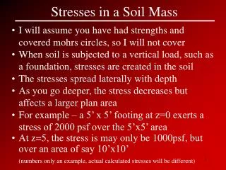
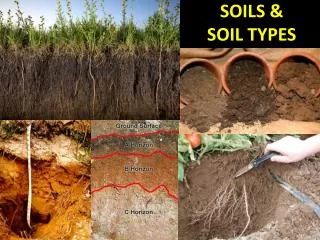
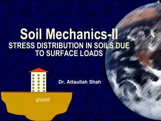
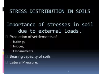
STRESS DISTRIBUTION IN SOILSImportance of stresses in soil due to external loads. • Prediction of settlements of • buildings, • bridges, • Embankments • Bearing capacity of soils • Lateral Pressure.
THEORY OF ELASTICITY • In Engineering mechanics, strain is the ratio of deformation to length and has nothing to do with working out. In an elastic material such as steel, strain is proportional to stress, which is why spring scales work. • Soil is not an ideal elastic material, but a nearly linear stress-strain relationship exists with limited loading conditions. • A simplification therefore is made that under these conditions soil can be treated mathematically during vertical compression as an elastic material. (The same assumption frequently is made in finite element analyses.)
Soil is considered ‘‘quasi-elastic,’’ or is described as exhibiting ‘‘near-linear elastic behavior. • There is a limit to near-linear elastic behavior of soils as loading increases and shearing or slipping between individual soil particles increases. • When that happens any semblance to an elastic response is lost as shearing more closely simulates plastic behavior. • This is the behavioral mode of soils in landslides, bearing capacity failures, and behind most retaining walls
The extent of the elastic layer below the surface loadings may be any one of the following: • Infinite in the vertical and horizontal directions. • Limited thickness in the vertical direction underlain with a rough rigid base such as a rocky bed. • The loads at the surface may act on flexible or rigid footings. The stress conditions in the elastic layer below vary according to the rigidity of the footings and the thickness of the elastic layer. • All the external loads considered are vertical loads only as the vertical loads are of practical importance for computing settlements of foundations.
I. The Bulb of Pressure Force “what are the stresses at this point?”
II. The Boussinesq EquationA. Goal: to determine the vertical and horizontal stresses under a point load in a homogeneous, isotropic medium. • Allows us to determine vertical and horizontal stresses at any point in space • Examine the transmission and distribution of stresses in large, extensive masses • of soil. Culvert?
II. The Boussinesq EquationB. The Equation: Where v = Poisson’s Ratio (0.48)
BOUSSINESCTS FORMULA FOR POINT LOADS • A semi-infinite solid is the one bounded on one side by a horizontal surface, here the surface of the earth, and infinite in all the other directions. The problem of determining stresses at any point P at a depth z as a result of a surface point load was solved by Boussinesq (1885) on the following assumptions. • The soil mass is elastic, isotropic (having identical properties in all direction throughout), homogeneous (identical elastic properties) and semi-infinite. • The soil is weightless. • The load is a point load acting on the surface. vertical stress бz, at point P under point load Q is given as • where, r = the horizontal distance between an arbitrary point P below the surface and the vertical axis through the point load Q. • z = the vertical depth of the point P from the surface. • IB - Boussinesq stress coefficient = • The values of the Boussinesq coefficient IB can be determined for a number of values of r/z. The variation of IB with r/z in a graphical form is given in Fig.
Problem • A concentrated load of 1000 kN is applied at the ground surface. Compute the vertical pressure • (i) at a depth of 4 m below the load, • (ii) at a distance of 3 m at the same depth. Use Boussinesq's equation. • Solve your self.
WESTERGAARD'S FORMULA FOR POINT LOADS • Actual soil is neither isotropic nor homogenous. • Westergaard, a British Scientist, proposed (1938) a formula for the computation of vertical stress бz by a point load, Q, at the surface as • in which µ, is Poisson's ratio. If µ, is taken as zero for all practical purposes, • The variation of /B with the ratios of (r/z) is shown graphically on next slide along with the Boussinesq's coefficient IB. The value of Iw at r/z = 0 is 0.32 which is less than that of IB by 33 per cent. • Geotechnical engineers prefer to use Boussinesq's solution as this gives conservative results.
Values of IB or Iw for use in the Boussinesq or Westergaard formula
Problem: Solve in the class • A concentrated load of 45000 Ib acts at foundation level at a depth of 6.56 ft below ground surface. • Find the vertical stress along the axis of the load at a depth of 32.8 ft and at a radial distance of • 16.4 ft at the same depth by • (a) Boussinesq, and • (b) Westergaard formulae for µ= 0. • Neglect the depth of the foundation.
LINE LOADS • By applying the principle of the above theory, the stresses at any point in the mass due to a line load of infinite extent acting at the surface may be obtained. • The state of stress encountered in this case is that of a plane strain condition. The strain at any point P in the Y-direction parallel to the line load is assumed equal to zero. The stress бy normal to the XZ-plane is the same at all sections and the shear stresses on these sections are zero. • The vertical бz stress at point P may be written in rectangular coordinates as • where, / z is the influence factor equal to 0.637 at x/z =0.
STRIP LOADS • Such conditions are found for structures extended very much in one direction, such as strip and wall foundations, foundations of retaining walls, embankments, dams and the like.
Fig. shows a load q per unit area acting on a strip of infinite length and of constant width B. The vertical stress at any arbitrary point P due to a line load of qdx acting at can be written from Eq. as • Applying the principle of superposition, the total stress бz at point P due to a strip load distributed over a width B(= 2b) may be written as • The non-dimensional values can be expressed in a more convenient form as
Example 6.4 • Three parallel strip footings 3 m wide each and 5 m apart center to center transmit contact pressures of 200, 150 and 100 kN/m2 respectively. • Calculate the vertical stress due to the combined loads beneath the centers of each footing at a depth of 3 m below the base. Assume the footings are placed at a depth of 2 m below the ground surface. Use Boussinesq's method for line loads.
PRESSURE ISOBARS-Pressure Bulb • An isobar is a line which connects all points of equal stress below the ground surface. In other words, an isobar is a stress contour. We may draw any number of isobars as shown in Fig. for any given load system. • Each isobar represents a fraction of the load applied at the surface. Since these isobars form closed figures and resemble the form of a bulb, they are also termed bulb of pressure or simply the pressure bulb. • Normally isobars are drawn for vertical, horizontal and shear stresses. The one that is most important in the calculation of settlements of footings is the vertical pressure isobar.
we may draw any number of isobars for any given load system, but the one that is of practical significance is the one which encloses a soil mass which is responsible for the settlement of the structure. • The depth of this stressed zone may be termed as the significant depth Ds which is responsible for the settlement of the structure. Terzaghi recommended that for all practical purposes one can take a stress contour which represents 20 per cent of the foundation contact pressure q, i.e, equal to 0.2q. • Terzaghi's recommendation was based on his observation that direct stresses are considered of negligible magnitude when they are smaller than 20 per cent of the intensity of the applied stress from structural loading, and that most of the settlement, approximately 80 per cent of the total, takes place at a depth less than Ds. • The depth Ds is approximately equal to 1.5 times the width of square or circular footings
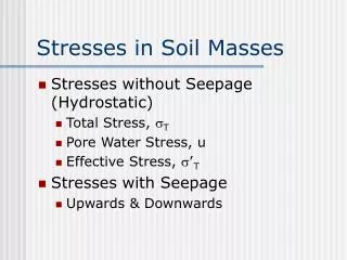
Effective Stress • Soil is a multi phase system • To perform any kind of analysis - we must understand stress distribution • The concept of effective stress: • The soil is “loaded” (footing for example) • The resulting stress is transmitted to the soil mass • The soil mass supports those stresses at the point to point contacts of the individual soil grains
Effective Stress The total stress at A is calculated from: The weight of the soil above A The weight of the water above A F = H*w + (HA - H) Vsat F = Total Stress at A Vw = Unit Weight of Water (62.4 pcf) Vsat = Saturated Unit Weight HA = Height of A to Top of water H = Height of water
Effective Stress • F is the stress applied to the soil by its own weight • As you go deeper in the soil mass, the stress increases • Like in a swimming pool, as you go deeper, the stress of the weight of the water increases • The soil carries the stress in 2 ways: • A portion is carried by the water (acts equally in all directions) • A portion is carried by the soil solids at their point of contact.
Effective Stress • The sum of the vert. components of the forces at their points of contact per unit of X- sectional area is the effective stress. an = Area of points of contact A = Cross Sectional area of soil mass Pn = Forces acting at points of contact
Effective Stress • The sum of vertical components of forces over the area is the effective stressF’ • F’= (P1v+P2v+P3v .....+Pnv) / A • If as = a1 + a2 + a3 +...an • Then the space occupied by water = A - as • Assume u = HA * Vw Ht of water * Vw= stress due to water (ft*pcf = psf = stress) • F = F’ + u(A - as) / A Since as is very small, assume 0 • F = F’ + u
Effective Stress Recall the following equation: F = H*w + (HA - H) *sat Now, F’ = F - u Substituting: F’ = [H*w + (HA - H) *sat] - HA * *w Rearranging: F’ = (HA - H)(*sat - *w) Height of Soil Column * *’ Where *’ = *sat - *w *’ = EFFECTIVE UNIT WEIGHT Effective Stress is independent of height of water In the equation: F = F’ + u F’ is the soil skeleton stress u is the stress in the water, or pore water pressure