Download
1 / 52
630 likes | 1.17k Vues
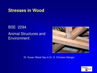
Stresses in Wood. BSE 2294 Animal Structures and Environment. Dr. Susan Wood Gay & Dr. S. Christian Mariger. Stress is the internal resistance of a material to external forces. Stresses in this barn’s roof components are resisting the external force caused by the snow load.

E N D
Stresses in Wood BSE 2294 Animal Structures and Environment Dr. Susan Wood Gay & Dr. S. Christian Mariger
Stress is the internal resistance of a material to external forces. Stresses in this barn’s roof components are resisting the external force caused by the snow load.
Wood members must resist five basic types of stresses. • Tension • Compression • Bearing • Shear • Bending Testing bearing stress in a wood member.
Stress in wood are adjusted for numerous factors. • Moisture content • Duration of load • Size and shape of cross-sectional area • Fire retardant treatment • Repetitive use Wood roof trusses in a dairy barn.
P P Tension is a pulling force acting along the length of the member. • Parallel to the grain • Tensile stress (Ft): • Tensile force on a member • Divided by the cross-sectional area of member • Ft = P/A Cross-sectional area (A) Example of a wood member under tension.
The bottom chords of triangular trusses are normally under tension. P P Example of the bottom chord of a truss under tension.
Tensile Stress Example Determine the tensile stress developed in a 2 by 4 under a load of 5000 lbs.
1. Calculate the cross-sectional area (A) of the board. A = W x L A = 1.5 in x 3.5 in = 5.25 in2
2. Calculate the tensile stress (Ft). Ft = P A Ft = 5000 lbs = 952 psi 5.25 in2
Compression is a pushing force acting along the length of a member. • Parallel to the grain • Compressive stress (Fc||): • Compressive force on member • Divided by the cross-sectional area of member • Fc|| = P/A Cross-sectional area (A) P P Example of a wood member in compression.
Posts are an example of wood members under compression. P P Example of a post under compression.
Compressive Stress Example Determine the maximum compressive load, parallel to the grain, that can be carried by a 2 by 6 No. 2, dense, Southern Pine without failure.
1. Find the maximum compressive force parallel (Fc||)to the grain from the Southern Pine Use Guide. Fc|| = 1750 psi
2. Calculate the cross-sectional area (A). A = W x L A = 1.5 in x 5.5 in = 8.25 in2
3. Calculate the maximum compressive load (P). Fc|| = P A P = Fc|| x A P = 1750 lbs/in2 x 8.25 in2 = 14,440 lbs
Bearing is a pushing force transmitted across the width of a structural member. • Perpendicular to the grain • Bearing stress (Fc^): • Bearing force on member • Divided by the contact area • Fc^= P/A P Contactarea (A) Example of bearing force on a wood member.
Rafters often carry a bearing loads. P Example of bearing stress on a structural member – where the bottom chord of the truss meets the rafter.
1000 lb Bearing Stress Example Determine the bearing stress developed in the beam caused by the loading as shown. The 2 by 6 beam is supported on both ends by 2 by 4’s.
1. Calculate the contact area (A) where the bearing stress is applied. A = W x L A = 1.5 in x 3.5 in = 5.25 in2
2. Calculate the bearing stress (Fc^). Fc^ = P A Fc^ = 1000 lb = 191 psi 5.25 in2
Shear force is the force that produces an opposite, but parallel, sliding motion of planes in a member. • Parallel to grain • Shear stress (Fv): • Shear force on beam • Divided by the shear area (area parallel to the load) • Fv = P/As Shear area (As) P P Example of bearing force on a wood member.
Shear stresses can occur in either the horizontal or vertical direction. Horizontal shear Vertical shear Vertical and horizontal shear in a wood member.
Shear Stress Example Determine the horizontal shear stress in an 8 ft long, 2 by 4 caused by a shear force of 5,000 lbs.
1. Calculate the shear area (As). As = W x L As = 1.5 in x 8 ft(12 in/1 ft) = 144 in2
2. Calculate the shear stress (Fv). Fv = P As P = 5000 lb = 34.7 psi 144 in2
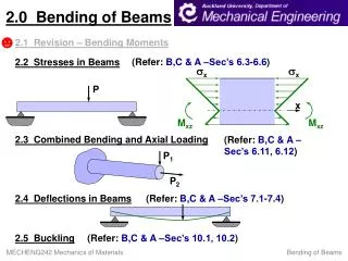
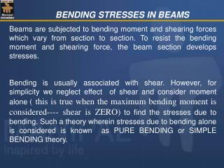
P Bending force is a force applied to a member in such a way as cause the member to bend. • Perpendicular to longitudinal axis • Bending stress (Fb): • Bending moment (M) on beam • Divided by section modulus (bh2/6) of the beam • Fb = 6M/bh2 Example of bending in a wood member.
The moment of inertia (I) is related to how an object’s mass is distributed as it rotates around an axis. • For a rectangle, I = bh3(in4) 12 • b = beam thickness • h = beam width h b The moment of inertia of a rectangle.
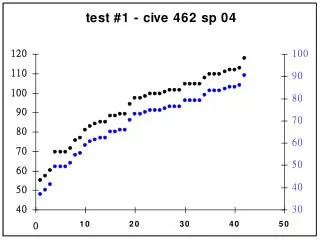
The modulus of elasticity (E) is the amount a member will deflect in proportion to an applied load. • Stiffness of material • Effect of cross-sectional shape on resistance to bending • Slope of stress-strain curve, E (lb/in2) Yield point Stress E Strain Cantilever beam, concentrated load.
The equations for a simply supported beam, concentrated load are: • Bending moment, M = PL 4 • Deflection, Δ = PL3 48EI • Note: L, b, and h are in inches. P L Simply supported, concentrated load.
W (lb/ft) L The equations for a simply supported beam, distributed load are: • Bending moment, M = WL2 8 • Deflection, Δ = 5WL4 384EI Simply supported, distributed load.
P L The equations for a cantilever beam, concentrated load are: • Bending moment, M = PL • Deflection, Δ = PL3 3EI Cantilever beam, concentrated load.
W (lb/ft) L The equations for a cantilever beam, distributed load are: • Bending moment, M = WL2 2 • Deflection, Δ = WL4 8EI Cantilever beam, distributed load.
Bending Stress Example #1 Determine the quality (No. 1, 2, or 3) of Southern pine required for a post that would be used for the application in the figure below. 200 lb 6 in x 6 in rough-cut post 15 ft
1. Calculate the bending moment (M). M = P x L (in) M = 200 lb x 15 ft(12 in/ft) = 36,000 in-lb
2. Calculate the bending stress (Fb). Fb= 6M bh2 Fb = (6)(36,000 in-lb) = 1000 psi (6 in) (6 in)2
2. Find the grade of lumber from Table #2 of the Southern Pine Use Guide. Fb > 1000 psi for No. 1
Deflection Example #1 Determine the deflection of the post used in the previous problem caused by the 200 lb load.
1. Calculate the moment of inertia (I). I = bh3 12 I = (6 in) (6 in)3 = 108 in4 12
2. Calculate deflection (Δ). Δ = PL3 3EI Δ = (200 lb) [(15 ft)(12in/ft)]3 = 2.4 in (3)(1500000 lb/in2)(108 in4)
Deflection Example #2 Determine the bending stress and the deflection if the post is a dressed 6 by 6.
1. Calculate the bending stress (Fb). Fb= 6M bh2 Fb = (6)(36,000 in-lb) = 1298 psi (5.5 in)(5.5 in)2
2. Calculate the moment of inertia (I). I = bh3 12 I = (5.5 in)(5.5 in)3 = 76.3 in4 12
3. Calculate deflection (Δ). Δ = PL3 3EI Δ = (200 lb) [(15 ft)(12in/ft)]3 = 3.4 in (3)(1500000 lb/in2)(76.3 in4)
Deflection Example #3 Determine the deflection in a 14-ft long, 2 by 12 floor joist caused by a total load of 60 psf. The joists are on 16” on center (OC) E = 1,200,000 psi. The design criteria are Δmax = L/360.
1. Calculate the load on one floor joist. W = (60 lb/ft2)(ft/12 in)2 x (16 in) = 6.7 lb/in
2. Calculate the moment of inertia (I). I = bh3 12 I = (1.5 in)(11.25 in)3 = 178 in4 12
3. Calculate the deflection (Δ). Δ = 5WL4 384EI Δ = (5)(6.67 lb/in)(168 in)4 = 0.33 in (384)(1,200,000 lb/in2)(178 in4)
4. Check design criteria. Δmax = L/360 Δmax = 168 in/360 = 0.47 in Δactual = 0.33 in Δactual <Δmax , design is adequate
Bending Stress Example #2 Would the floor joist from the previous problem work if the design is based on stress? For No. 1 Southern pine, Fb =1250 psi.
1. Calculate the bending moment (M). M = WL2 8 M = (6.7 lb/in)(168 in)2 = 23,638 in-lb 8