Download
1 / 9
100 likes | 368 Vues
Shear Stresses in Concrete Beams. Stresses Near Support. x. Near Top. y. Max. tensile stresses a few degrees clockwise. x. Mid-height. Max tensile stress 45 °. y. Max. tensile stresses a few degrees ccw. x. Near bottom. y. Shear Failure Path.

E N D
Stresses Near Support x Near Top y Max. tensile stresses a few degrees clockwise x Mid-height Max tensile stress 45° y Max. tensile stresses a few degrees ccw x Near bottom y
Shear Failure Path Vertical reinforcing steel, shear stirrups, are added to resist the portion of the shear force not resisted by the concrete.
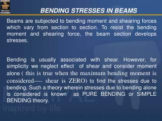
Shear Strength of Concrete The shear strength of a reinforced concrete beam is a result of the dowel force, aggregate interlock, and shear compression force. f’c in psi
Shear Strength of Steel Stirrups where, s = stirrup spacing Av = total cross-sectional area of the vertical legs of one stirrup For equilibrium: where, Ф = 0.75 For design:
ACI Limitations on Stirrup Spacing • s ≤ ½ d if , f’c in psi. And for beams and girders if • s ≤ ¼ d if (upper limit on Vs) • ,fy in ksi and Av in in2 • s < 3 in. to allow placement of concrete
Shear Analysis • Coefficients for shear given on p. 19 of notes or Part 5 of Manual of Steel Construction • If a beam or girder is supported in such a way that vertical compression is induced in the bottom, as will be the case if support is provided by a column or a considerably deeper member, the shear force a distance d from the support is used for design.
Design of Shear Reinforcementfor Previous Example p. 21 notes The partial office building floor plan shown had beams spanning 30 ft and girders spanning 24 ft. Design the slab, beams, and girders to support a live load of 80 psf and a dead weight of 15 psf in addition to the self weight of the structure. Use grade 60 reinforcing steel and 4000 psi concrete. 30 ft 30 ft 30 ft 30 ft 24 ft 24 ft 24 ft