Download
1 / 26
260 likes | 578 Vues
Learn how shearing stresses impact beams & thin-walled members. Detailed examples & solutions provided for practical understanding.

E N D
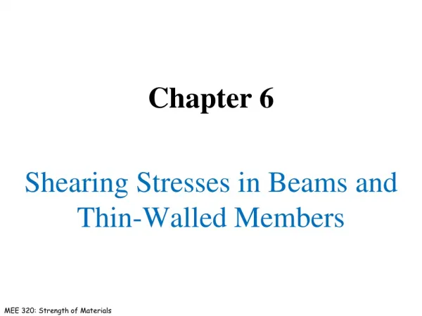
6 Shearing Stresses in Beams and Thin-Walled Members
Shearing Stresses in Beams and Thin-Walled Members Introduction Shear on the Horizontal Face of a Beam Element Example 6.01 Determination of the Shearing Stress in a Beam Shearing Stresses txy in Common Types of Beams Further Discussion of the Distribution of Stresses in a ... Sample Problem 6.2 Longitudinal Shear on a Beam Element of Arbitrary Shape Example 6.04 Shearing Stresses in Thin-Walled Members Plastic Deformations Sample Problem 6.3 Unsymmetric Loading of Thin-Walled Members Example 6.05 Example 6.06
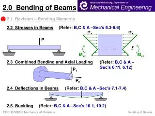
Transverse loading applied to a beam results in normal and shearing stresses in transverse sections. • Distribution of normal and shearing stresses satisfies • When shearing stresses are exerted on the vertical faces of an element, equal stresses must be exerted on the horizontal faces Introduction • Longitudinal shearing stresses must exist in any member subjected to transverse loading.
For equilibrium of beam element • Note, • Substituting, Shear on the Horizontal Face of a Beam Element • Consider prismatic beam
Shear flow, • where • Same result found for lower area Shear on the Horizontal Face of a Beam Element
Example 6.01 • SOLUTION: • Determine the horizontal force per unit length or shear flow q on the lower surface of the upper plank. • Calculate the corresponding shear force in each nail. A beam is made of three planks, nailed together. Knowing that the spacing between nails is 25 mm and that the vertical shear in the beam is V = 500 N, determine the shear force in each nail.
SOLUTION: • Determine the horizontal force per unit length or shear flow q on the lower surface of the upper plank. • Calculate the corresponding shear force in each nail for a nail spacing of 25 mm. Example 6.01
The average shearing stress on the horizontal face of the element is obtained by dividing the shearing force on the element by the area of the face. • On the upper and lower surfaces of the beam, tyx= 0. It follows that txy= 0 on the upper and lower edges of the transverse sections. Determination of the Shearing Stress in a Beam • If the width of the beam is comparable or large relative to its depth, the shearing stresses at D1 and D2 are significantly higher than at D.
For a narrow rectangular beam, • For American Standard (S-beam) and wide-flange (W-beam) beams Shearing Stresses txyin Common Types of Beams
Consider a narrow rectangular cantilever beam subjected to load P at its free end: • From Saint-Venant’s principle, effects of the load application mode are negligible except in immediate vicinity of load application points. • Stress/strain deviations for distributed loads are negligible for typical beam sections of interest. Further Discussion of the Distribution of Stresses in a Narrow Rectangular Beam • Shearing stresses are independent of the distance from the point of application of the load. • Normal strains and normal stresses are unaffected by the shearing stresses.
Sample Problem 6.2 • SOLUTION: • Develop shear and bending moment diagrams. Identify the maximums. • Determine the beam depth based on allowable normal stress. A timber beam is to support the three concentrated loads shown. Knowing that for the grade of timber used, • Determine the beam depth based on allowable shear stress. • Required beam depth is equal to the larger of the two depths found. determine the minimum required depth d of the beam.
Sample Problem 6.2 SOLUTION: Develop shear and bending moment diagrams. Identify the maximums.
Determine the beam depth based on allowable normal stress. • Determine the beam depth based on allowable shear stress. • Required beam depth is equal to the larger of the two. Sample Problem 6.2
Consider prismatic beam with an element defined by the curved surface CDD’C’. • Except for the differences in integration areas, this is the same result obtained before which led to Longitudinal Shear on a Beam Element of Arbitrary Shape • We have examined the distribution of the vertical components txy on a transverse section of a beam. We now wish to consider the horizontal components txz of the stresses.
Example 6.04 • SOLUTION: • Determine the shear force per unit length along each edge of the upper plank. • Based on the spacing between nails, determine the shear force in each nail. A square box beam is constructed from four planks as shown. Knowing that the spacing between nails is 1.5 in. and the beam is subjected to a vertical shear of magnitude V = 600 lb, determine the shearing force in each nail.
For the upper plank, • Based on the spacing between nails, determine the shear force in each nail. For the overall beam cross-section, Example 6.04 • SOLUTION: • Determine the shear force per unit length along each edge of the upper plank.
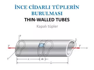
The longitudinal shear force on the element is • The corresponding shear stress is • Previously found a similar expression for the shearing stress in the web • NOTE: in the flanges in the web Shearing Stresses in Thin-Walled Members • Consider a segment of a wide-flange beam subjected to the vertical shear V.
The variation of shear flow across the section depends only on the variation of the first moment. Shearing Stresses in Thin-Walled Members • For a box beam, q grows smoothly from zero at A to a maximum at C and C’ and then decreases back to zero at E. • The sense of q in the horizontal portions of the section may be deduced from the sense in the vertical portions or the sense of the shear V.
Shearing Stresses in Thin-Walled Members • For a wide-flange beam, the shear flow increases symmetrically from zero at A and A’, reaches a maximum at C and the decreases to zero at E and E’. • The continuity of the variation in q and the merging of q from section branches suggests an analogy to fluid flow.
Recall: • For PL > MY , yield is initiated at B and B’. For an elastoplastic material, the half-thickness of the elastic core is found from • The section becomes fully plastic (yY = 0) at the wall when • Maximum load which the beam can support is Plastic Deformations • For M = PL < MY , the normal stress does not exceed the yield stress anywhere along the beam.
Preceding discussion was based on normal stresses only • Consider horizontal shear force on an element within the plastic zone, Therefore, the shear stress is zero in the plastic zone. • Shear load is carried by the elastic core, Plastic Deformations • As A’ decreases, tmax increases and may exceed tY
SOLUTION: • For the shaded area, • The shear stress at a, Sample Problem 6.3 Knowing that the vertical shear is 50 kips in a W10x68 rolled-steel beam, determine the horizontal shearing stress in the top flange at the point a.
Beam loaded in a vertical plane of symmetry deforms in the symmetry plane without twisting. • Beam without a vertical plane of symmetry bends and twists under loading. Unsymmetric Loading of Thin-Walled Members
If the shear load is applied such that the beam does not twist, then the shear stress distribution satisfies • F and F’ indicate a couple Fh and the need for the application of a torque as well as the shear load. • When the force P is applied at a distance e to the left of the web centerline, the member bends in a vertical plane without twisting. Unsymmetric Loading of Thin-Walled Members
Determine the location for the shear center of the channel section with b = 4 in., h = 6 in., and t = 0.15 in. • where • Combining, Example 6.05
Shearing stresses in the flanges, • Shearing stress in the web, Example 6.06 • Determine the shear stress distribution for V = 2.5 kips.