Download
1 / 24
270 likes | 424 Vues
Explore the classification, materials, and design aspects of fiber reinforced concrete coupling beams for earthquake-resistant structures. Learn about shear contribution, behavior, and the potential elimination of diagonal bars for efficient design.

E N D
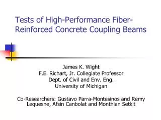
FIBER REINFORCED CONCRETE IN SHEAR WALL COUPLING BEAMS Gustavo J. Parra-MontesinosC.K. Wang Professor of Structural EngineeringUniversity of Wisconsin-MadisonJames K. WightFrank E. Richart Jr. Collegiate ProfessorUniversity of MichiganCary KopczynskiPrincipal, Cary Kopcyznski & Co.
OUTLINE • Current design practice for coupling beams • Research motivation • Classification of Fiber Reinforced Concretes (FRCs) • Experimental program • Coupling beams • Coupled walls • Implementation of fiber reinforced concrete coupling beams into practice
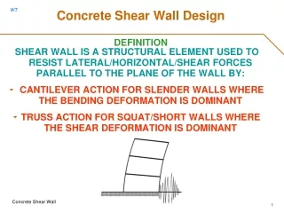
COUPLED WALLS • Two or more walls connected by short beams referred to as coupling beams • Commonly used in medium- and high-rise structures in combination with RC or steel moment frames
CURRENT COUPLING BEAM DESIGN PRACTICE IN USA • Typical span-to-depth ratios between 1.5 and 3.5 • Diagonal reinforcement, designed to carry the entire shear demand, is required in most cases • Column-type transverse reinforcement must be provided to confine either diagonal reinforcement or entire member • Maximum shear stress of 10√fc’ (psi) • Little longitudinal reinforcement, terminated at the wall near the coupling beam end
TYPICAL COUPLING BEAM DESIGN (Lequesne, Parra and Wight)
MOTIVATION • Reinforced concrete coupling beams require intricate reinforcement detailing to ensure stable seismic behavior, leading to severe congestion and increased construction cost • Use of a material with tension ductility and confined concrete-like behavior should allow for substantial simplification in confinement and shear reinforcement without compromising seismic behavior
FIBER REINFORCED CONCRETE • Concrete reinforced with discontinuous fibers • Commonly used steel fibers have deformations to improve bond with surrounding concrete. However, fibers are ultimately expected to pullout
MATERIAL-RELATED ASPECTS Constituents Concrete matrix in fiber reinforced concrete is made of same constituents used in plain concrete • Aggregates (fine and course) • Cement • Water • Mineral admixtures • Water reducing agents (high-range water-reducing agents)
MATERIAL-RELATED ASPECTS Aggregates • Sufficient fine aggregates to ensure adequate volume of paste • Control volume and size of course aggregate • Increase in course aggregate size has been associated with poor fiber distribution and a reduction in tensile performance • Maximum aggregate size in fiber reinforced concrete used in coupling beams has been limited to ½ in. Workability • For large fiber dosages as used in coupling beams, use self-consolidating mixture or a mixture with high slump (at least 8 in.) prior to addition of fibers
USE OF SELF-CONSOLIDATING HPFRC • Regular concrete matrix (1/2 in. max. aggregate size) • 1.5% volume fraction of high-strength hooked steel fibers (lf=1.2 in.; df = 0.015 in.) (Naaman et al.)
CLASSIFICATION OF FRCs • Based on bending and tension behavior • Strain hardening vs. softening • Deflection hardening vs. softening (Naaman and Reinhardt 2003)
FIBER REINFORCED CONCRETE IN EARTHQUAKE-RESISTANT COUPLING BEAMS • Fiber reinforced concrete with tensile strain-hardening behavior (HPFRC) and compression behavior similar to well-confined concrete RC HPFRC
FIBER REINFORCED CONCRETE IN EARTHQUAKE-RESISTANT COUPLING BEAMS High-strength hooked steel fibers have been the most investigated fiber type for use in coupling beams Volume fraction = 1.5% (200 lbs/cubic yard)
SLENDER COUPLING BEAM (ln/h = 2.75) • Target shear stress 8-10√f’c , psi • Approximately 25% of shear resisted by diagonal bars , 45% of shear carried by stirrups, and 30% of shear resisted by HPFRC • Transverse reinforcement ratio = 0.56%
SHEAR CONTRIBUTION FROM DIAGONAL BARS CB-1 CB-2 CB-3
ELIMINATION OF DIAGONAL BARS (ln/h ≥ 2.2) COUPLING BEAM BEHAVIOR • Complete elimination of diagonal reinforcement in coupling beams with length-to-depth ratios ≥ 2.2 • No special confinement, except for beam ends • Shear strength up to 10√f’c (psi) (Sektik, Parra and Wight)
SLENDER COUPLING BEAM DESIGN (ln/h ≥ 2.2) COUPLING BEAM BEHAVIOR (Sektik, Parra and Wight)
BEHAVIOR of COUPLING BEAM with NO DIAGONAL BARS (ln/h = 3.3) (Sektik, Parra and Wight)
SLENDER COUPLING BEAM with NO DIAGONAL BARS AT 6% DRIFT (Sektik, Parra and Wight)
BEHAVIOR of COUPLING BEAM with NO DIAGONAL BARS (ln/h = 2.2) (Comforti, Parra and Wight)
CONCLUSIONS – SLENDER COUPLING BEAMS • When diagonal reinforcement was used in slender HPFRC coupling beams, shear resistance provided by that reinforcement was estimated at or below 15% of the total shear, which suggested elimination of diagonal bars in such beams • Diagonal bars can be eliminated in HPFRC coupling beams with ln/h ≥ 2.2 when reinforced with a 1.5% volume fraction of high-strength hooked steel fibers and subjected to shear stress demands up to the upper limit in ACI Building Code