FIBER REINFORCED CONCRETE
390 likes | 2.37k Vues
FIBER REINFORCED CONCRETE. Presented By MOHD HUZAIFA YAMAN IIIrd Year II Sem.

FIBER REINFORCED CONCRETE
E N D
Presentation Transcript
FIBER REINFORCED CONCRETE Presented By MOHD HUZAIFA YAMAN IIIrd Year II Sem
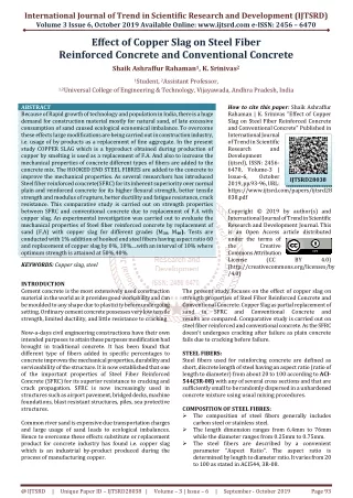
The fundamental aim of this work is to give clear guidelines for the process of strengthening reinforced concrete beams using FRP materials. Types and methods of FRP construction are described in general. FRP properties and their effect on strengthening are illustrated. Experimental results obtained from an earlier study are utilized in this research to present a reasonable model for strengthening. The experiments investigated the shear behavior of reinforced concrete beams strengthened by the attachment of different configurations and quantities of CFRP using epoxy adhesives. Two types of CFRP materials were used. These are pultruded and prepreg materials. A general comparison between results is carried out showing the best configuration for strengthening. Keywords: Strengthening, Beams, Polymer Plates, Fiber-Reinforced Polymer (FRP). ABSTRACT
What is FRP Reinforcement? fiber reinforced plastic (FRP) reinforcement is one of the most promising new developments for concrete structures. FRP reinforcing elements provide lighter, easier to assemble, and more durable structures that are free of the deterioration caused by corrosion of steel. FRPsconsist of synthetic or organic high strength fibers, most of which are impregnated with a resin matrix. They are available in the form of grids, rods, and ropes for reinforcing and restressing concrete members
The general advantages of FRP reinforcement compared to steel are: • High ratio of strength to mass density (10 to 15 times greater than steel's). • Carbon and aramid fiber reinforcement have excellent fatigue characteristics (as much as three times higher than steel's). (However, the fatigue strength of glass FRP reinforcement may be significantly below steel's). • Excellent corrosion resistance and electromagnetic neutrality. • Low axial coefficient of thermal expansion, especially for carbon fiber reinforced composite materials. ADVANTAGES
Disadvantages of FRP reinforcement include: • High cost (S to 50 times more than steel) • Low modulus of elasticity • Low failure strain • Special attention must be paid to anchorages when FRP reinforcement is used for prestressing (because of FRP' s high ratio of axial to lateral strength). • Long-term strength ofFRP reinforcement can be lower than short-term static DISADVANTAGES
Differences between FRP and Steel FRP composites are different from steel in that they possess properties that can vary in different directions (anisotropic), whereas steel has similar properties in all directions (isotropic). The most common type of fiber sheets for concrete strengthening application are constructed with continuous unidirectional carbon or glass fiber that runs the length of the fabric. When loaded in direct tension, unidirectional FRP materials exhibit a linear-elastic stress-strain relationship until failure, with no yielding or plastic behavior. Due to the linear-elastic characteristics of FRP and the fact they are applied externally to structural elements, the standard methods used to design or determine the amount of steel reinforcement do not apply to FRP. Relatively more complex procedures are used to design FRP, which can involve iterative design methodology.
TYPES OF FRP There are two types of FRP Reinforcement 1. PULTRUDED FRP Pultrusion is a technique for the continuous manufacture of fiber reinforced composite profiles. By incorporating glass, carbon, aramid or other high performance fibers into a range of high performance resins, physical properties can be achieved to meet the needs of engineers in a wide variety of applications. 2. PREPREG FRP Pre-impregnated materials (prepregs) provide the most precise way of combining reinforcements with the resin matrix. Prepregs are semi-finished products with unidirectional single layers of fiber (with all the fibres in this layer aligned parallel to each other) or woven fibers pre-impregnated with resin (several directions of reinforcement).
Pultruded Carbon Fibers. Prepreg Carbon Fiber.
TEST PROGRAMME • A series of 38 beams were produced, all of which were designed to fail in shear. These were strengthened using CFRP methods in various configurations in combination with other factors. The variables were: • • Percentage main (bottom) reinforcement. • • Link spacing in shear span. • • Configuration of CFRP strengthening. • The materials used were as follows: • • Concrete with an average 150mm cube strength fcu = 61.8 MPa. • • Hot-rolled high yield deformed main reinforcement with a strength of fy = 420 MPa. • • Sika Carbo Dur S1012 pultruded unidirectional CFRP material of 100 mm width and 1.2 mm thickness, fiber volume = 68% in an epoxy matrix, ultimate tensile strength (UTS) = 3100 N/mm2 and modulus of elasticity = 155 kN/mm2 bonded with Sikadur 30 (beams B2-B14). • • SikaWrap Hex 103C CFRP fabric, 0.27 mm thick, UTS = 3500 MPa bonded with Sikadur 330 (beams B15-B16).
RESULTS The control beam B1, beams B3-B4 with CFRP on the soffits, beam B5 and those strengthened with SikaWrap all failed by the development of shear cracks in the concrete . The failure of the beams with plates over the entire shear span (B11-B14) was explosive with little warning and probably compressive in nature. All remaining specimens, reinforced with CFRP strips, failed due to shear and delamination of the strips .In all cases, failure occurred in the concrete rather than the adhesive, thus emphasizing how important it is to adequately anchor the strips on each
CONCLUSIONS Advanced composites are increasingly being used in the construction industry due to their inherent advantages over traditional materials including their lightweight, high strength, ease of application and low maintenance costs. The conclusions below embrace practical recommendations for strengthening reinforced concrete beams in shear using CFRP plates and woven carbon fibre “wrap fibre”: • The Sikadur 30 adhesive bonded adequately with the concrete regardless of the curing method and surface treatment. In general, it is adequate to remove all laitance and loose material by hand or machine abrading, followed by degreasing with a detergent and rinsing clean. • The application of CFRP strips to the shear spans of the beams increased the strength between 19% (B8) and 56% (B2). The increase in strength was governed by the anchorage of the strips on each side of the projected shear crack. The application of two horizontal CFRP strips over the shear span and tension zone (such as beam B2) appears to be an efficient method of shear strengthening. • The greatest increase in shear strength was achieved by bonding plates over the entire depth and shear span (B11-B14). However, subsequent failure was sudden and with very little warning. • The application of SikaWrap 103C to the soffit and sides of the shear span increased the shear strength by 80-90%.