
Parametric Design for Industrial Staircases: Innovative Solutions for Efficiency
E N D
Presentation Transcript
Parametric Design William Foil Tyler Kennedy Advisors: Dr. ma and Dr. Saadeh Professor: Dr. Koutsougeras ET-493, Senior Design
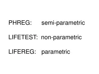
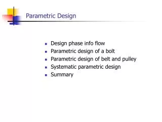
3-D Parametric Design • 3-D parametric design is a modeling approach that uses parameters to define features and relationships between parts • SOLIDWORKS is our chosen 3-D design software
Original Project: • Originally we were tasked with createing a 3-D parametric design for Hydroloxs’ Traveling Water Screen. • The problem: Drafter has to manually customize designs to fit the working conditions.
Original Project Solution: Create GUI to allow User to edit pre-existing parts
Current Application • Design plant layout optimization program for Lapeyre Stair • Elements from our parametric design program will be used
Lapeyre Stair • Part of Laitram L.L.C. • Involved in manufacturing and design of industrial stair cases and platforms • Purpose behind LapeyreStair: • Drastically reduces design time, • Reduced Construction costs • Reduced installation errors
Objective The Problem: • Platforms must be manually inserted The Solution: • Create program to plot platforms at user defined coordinates
Relevance to Engineering • Program Design • Force Calculations: static and dynamic • Knowledge and application of equations • Project Management
What We Accomplished • Created basic MatLABand Visual Basic (VBA) Graphical User Interface (GUI) • Establish connection between MatLAB, Excel, and SOLIDWORKS • Created a user interface to re-dimension a predefined object in SOLIDWORKS • Establish connections between VBA and SOLIDWORKS • Ported MatLAB program to VBA
Moving Forward • Insert pre-made parts at specific coordinates instead of shapes • Insert structural members and rails of platforms via user input