Download

1 / 28
280 likes | 405 Vues
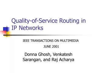
Quality of Service The Key Enabler for Real-Time Services in HRPD Networks. Sanket S. Nesargi sanket@nortel.com. Intent. Provide an overview of QoS support in the 3GPP2 network Components and interactions needed to support QoS in the air-interface, access and core networks

E N D
Quality of ServiceThe Key Enabler for Real-Time Services in HRPD Networks Sanket S. Nesargisanket@nortel.com
Intent • Provide an overview of QoS support in the 3GPP2 network • Components and interactions needed to support QoS in the air-interface, access and core networks • Interaction of QoS with Service Based Bearer Control • Provide Nortel’s view of evolving QoS in the 3GPP2 network • Evolving towards an End-to-End QoS model in a converged network • Enhancing QoS support at individual 3GPP2 network components • HRPD Rev A network used as illustrative example to identify defined QoS solutions
VoIP Session VoIP Application VoIP Application Calling Party Called Party Real Time ApplicationsThe Key Drivers for QoS Connection for voice bearer Connection for SIP signaling cdma2000 Packet Data Network Internet • QoS mechanisms defined in 3GPP2 • Focus of current presentation • Evolution needed for QoS to work seamlessly end-to-end QoS facilitated by IETF defined mechanisms such as DiffServ or IntServ
Signaling Path Bearer Path HSS CSCF MMD Domain PCRF AN PCF AAA PDSN HA cdma2000 Packet Data Network Architecture 3GPP2 Packet Core Network HRPD Air Interface 3GPP2 Radio Access Network
Signaling Path Bearer Path IP PPP Enet GRE 100BT IP IP PPP Enet 100BT RLP IP MAC Relay Relay HRPDPHY GRE GRE RLP GRE IP IP MAC IP Enet Enet Enet HRPDPHY 100BT 100BT 100BT AN PCF PDSN Interconnection Points & Protocol Stacks HRPD Air Interface Protocols Internet A9 A11 A10 A8 Application QoS (End-to-end QoS) Access QoS (Local Policy or RAN signaled) HRPD Air-Interface QoS Negotiation
Decomposing the InterfacesBetween the AT and the AN (1 of 2) Concepts: • Reservations: • Represent an “IP Flow” or “application flow” • Identified by an 8-bit ReservationLabel • Unidirectional in nature i.e., {0x02, fwd} not related to {0x02, rev} • Have associated Requested and Granted QoS • QoS parameters specified via blobs in attributes • Two states: “open” and “close” • Default reservation 0xff • assumed to be for best effort traffic • state set to “open” by default • Link Flows: • Represent RLP flows across air-interface • Unidirectional in nature • Identified by Link Flow ID • Two states: “activated” and “deactivated” • Can support protocol-stack characteristics such as PPP/HDLC removal, ROHC-framing, etc.
AN AT Decomposing the InterfacesBetween the AT and the AN (2 of 2) • Link Flows: • Individual RLP connections • Unidirectional • States: Activated, Deactivated • Reservations: • Individual IP Flows • Unidirectional • States: Open, Closed • Default reservation: 0xff always open Link Flow {0x01, fwd} Resv (0xff, fwd} Link Flow {0x01, rev} Resv (0xff, rev} Link Flow {0x02, fwd} Resv (0x04, fwd} QoS for fwd Flow 0x04 • Link flows • {0x02, fwd} & {0x03, rev} • Upper layer protocol set to PPP • PPP-encapsulated and HDLC-framed packets exchanged on these link flows Resv (0x05, fwd} QoS for fwd Flow 0x05 Link Flow {0x03, rev} Resv (0x08, rev} QoS for rev Flow 0x03 Link Flow {0x04, fwd} Resv (0x06, fwd} QoS for fwd Flow 0x06 • Link flows • {0x04, fwd} & {0x08, rev} • Upper layer protocol set to ROHC • link flow configured as ROHC channel • Raw ROHC packets exchanged on these link flows • Link flows tied together for purposes of ROHC feedback Link Flow {0x08, rev} Resv (0xa2, rev} QoS for rev Flow 0xa2 Multi Flow Packet Application Requested and Granted QoS Blobs associated with Reservations
AN PDSN PCF Decomposing the Interfaces The Access Interface • Main A10 connection • always carries{0xff, fwd} and {0xff, rev} • Service Option 59 Resv (0xff, fwd} Flow ID {0xff, fwd} A10 #0, SO 59 A8 #0, SO 59 Resv (0xff, rev} Flow ID {0xff, rev} Resv (0x02, fwd} Flow ID {0x02, fwd} A10 #1, SO 64 A8 #1, SO 64 Resv (0x05, fwd} Flow ID {0x05, fwd} • Auxiliary A10 connection • Service Option 64 • PPP-encapsulated & HDLC framed traffic A8 #2, SO 64 A10 #2, SO 64 Resv (0x03, rev} Flow ID {0x03, rev} Resv (0x06, fwd} Flow ID {0x06, rev} A8 #3, SO 67 A10 #3, SO 67 Resv (0xa2, rev} Flow ID {0xa2, rev} • Auxiliary A10 connection • Service Option 67 • raw IP or ROHC packets
AN AT PDSN PCF AAA Signaling Interactions Flow Setup Example 1. Establish HRPD Session and default reservation 0xFF 2. A8/A10 Established for main service instance (SO 59) Subscriber QoS profile contains user specific information such as allowed DSCP, SOs 3. PPP Established 4. Retrieve subscriber-QoS profile from Home AAA 5. Subscriber-QoS Profile Transferred 6. Reservations with requested QoS parameters Admission control is performed based on available radio resources and subscriber profile received from PDSN New A8/A10 connections and link flows are established based by AN based on local resource constraints/policies AT initiates establishment of IP flows based on application needs 7. QoS-based Admission Control 8. Granted QoS parameters provided RLP Established (if needed) 8. IP-flow mapping information conveyed A8/A10 Established – SO 64/67 (if needed) TFT’s define packet filters to enable PDSN identify Flow ID of incoming packets 9. RSVP-like exchange to establish Non-specific TFT for flow at PDSN
AN AT PCRF P-CSCF PDSN AAA Signaling Interactions Flow Setup Example with Service Based Bearer Control (SBBC) (1 of 3) 1. Establish HRPD Session and default reservation 0xFF 2. A8/A10 Established for main service instance (SO 59) 3. PPP Established 4. Retrieve subscriber-QoS profile from Home AAA 5. Subscriber-QoS Profile Transferred SIP Invite SIP Invite 6. SIP signaling to initiate call setup 183 Progress 183 Progress
AN AT PCRF P-CSCF PDSN Signaling Interactions Flow Setup Example with Service Based Bearer Control (SBBC) (2 of 3) 7. Download session charging and Authorized QoS information 8. Request for bearer flow based on step 6 with QoS parameters 9. QoS Flow Admission Control based on Subscriber Profile 10. Granted QoS parameters provided and link flow Established (if needed) 11. IP-flow mapping information conveyed. A8/A10 Established (if needed) 12. TFT Establishment - Flow information included (Resv) 13. Flow information requested from PCRF 13. Flow information retrieved from home PCRF (if not available locally)
AN AT PCRF P-CSCF PDSN Signaling Interactions Flow Setup Example with Service Based Bearer Control (SBBC) (2 of 3) 14. QoS comparison between Granted and Session QoS 15. TFT Establishment Ack (ResvConf) 16. Updated Granted QoS conveyed to AN based on Step 14 17. Updated Granted QoS conveyed to AT 18. Remainder SIP signaling to set up the call and establish the bearer
IP PPP Enet GRE 100BT IP IP PPP Enet 100BT RLP IP MAC Relay Relay HRPDPHY GRE GRE RLP GRE IP IP MAC IP Enet Enet Enet HRPDPHY 100BT 100BT 100BT AN PCF PDSN Applying QoS Treatments on the BearerForward Path • PDSN uses packet filters in TFT to identify Flow ID corresponding to packet • PDSN places packet on A10 connection for the Flow ID specified by AN Packet arrives from the Internet HRPD Air Interface Protocols Internet A9 A11 A10 A8 • PDSN marks outer IP header of packet with DSCP based on: • local policy OR • copying inner IP DSCP to outer header OR • using DSCP marking for Flow ID specified by RAN AN uses QoS treatment established for Flow ID to forward packet across air interface PCF copies DSCP marking from incoming packet to outgoing packet
IP PPP Enet GRE 100BT IP IP PPP Enet 100BT RLP IP MAC Relay Relay HRPDPHY GRE GRE RLP GRE IP IP MAC IP Enet Enet Enet HRPDPHY 100BT 100BT 100BT AN PCF PDSN Applying QoS Treatments on the BearerReverse Path Packet arrives from the AT HRPD Air Interface Protocols Internet A9 A11 A10 A8 • AN marks outer IP header of packet with DSCP based on: • local policy OR • copying inner IP DSCP to outer header AT uses QoS treatment established for Flow ID in reverse direction across the air interface PDSN forwards packets to the Internet based on DSCP associated with inner IP header PCF copies DSCP marking from incoming packet to outgoing packet
Relay Relay GRE Enet GRE GRE GRE RLP RLP IP 100BT IP IP IP MAC MAC Enet Enet Enet Enet HRPD Phy HRPD Phy 100BT 100BT 100BT 100BT IP IP IP Relay Enet GRE GRE GRE GRE RLP RLP IP 100BT IP IP IP MAC MAC Enet Enet Enet Enet HRPD Phy HRPD Phy 100BT 100BT 100BT 100BT Bearer Path Protocol Stacks for Real-time Services No PPP encapsulation or HDLC-like framing on the bearer path Header Compression at the PDSN IP IP ROHC ROHC PDSN PCF AT AN • ROHC compression done at PDSN, AT • Raw ROHC packets exchanged between PDSN and AT • No PPP encapsulation or HDLC-like framing on the bearer path Header Compression at the RNC ROHC ROHC PDSN PCF AT AN • ROHC compression done at AN, AT • Raw ROHC packets exchanged between AN and AT
Application IP QoS Application Servers AAA, AN-AAA, DNS, DHCP IPhost HRPD RNC OAM MMD Internet backhaultransportserviceedge AT FW/BG Private IP network IPhost BTS Intranet DSDomainEdge PDSN(FA) Application Servers DSDomainEdge HA RAN QoSDomainEdge Application Servers Wireless Operator’s IP QoS Domain Facilitating End-to-End QoS • Support needed to facilitate end-to-end QoS: • Consistent packet treatments • access edge and service provider boundaries • general packet filtering (DSCP/ToS, IP address, port number) • traffic conditioning: policing, shaping, marking, dropping • congestion avoidance • scheduling • Admission control - based on local and network conditions • Signalling - to convey information regarding network conditions • Security - to prevent unauthorized access to network resources • OA&M, including policy based management
Current QoS Approaches in the Internet • Integrated Services (IntServ) • QoS requirements for individual IP flows reserved at each hop • explicit signaling protocols (e.g., RSVP) to establish QoS state at intermediate routers • Scalability issues due to soft state storage requirements • Not widely deployed across the Internet – both in routers and at end hosts • Differentiated Services (DiffServ) • Per-hop Behaviors (PHBs) defined for multiple flows with similar QoS characteristics (Behavior Aggregate – BA) • PHBs identified by Differentiated Services Code Points (DSCPs) • QoS tasks distributed across network nodes – enhanced scalability • complex tasks viz., packet classification, traffic conditioning done at network edge • simple tasks viz., packet forwarding based on per hop behavior (PHB) performed at network core • Service Level Agreements (SLAs) established across DiffServ enabled domains
Limitations of Current QoS Approaches • PHBs only define characteristics of the forwarding behaviours • queuing disciplines (categories of queuing and scheduling algorithms) not defined • Additional mechanisms needed to ensure that traffic conditions required to provide PHBs are maintained • Consistent DSCP marking is far from pervasive in the application space For optimal application and service performance, QoS technologies must be implemented consistently across different networking technologies. Embodiment of any end to end QoS offering needs to completely define the collection of traffic conditioning rules and IP forwarding mechanisms required for each class
Network Service Classes (NSCs) • A set of Network Service Classes (NSCs) has been defined in draft-ietf-tsvwg-diffserv-service-classes-00 which define: • traffic management • performance management parameters for the most popular applications, including IP telephony, video, messaging, transaction processing, etc. • The IP host (client or server) has access to the QoS requirements for resident user applications. • Thus, IP host should mark the DSCP field of the IP packets appropriately • However, DSCP marking is far from pervasive in the application space • Standardization of draft-ietf-tsvwg-diffserv-service-classes-00 may help change this situation. Network Service Classes may provide a means to facilitate End-to-End QoS in 3GPP2 networks
Network Service Classes - Overview _ Default Forwarding (DF) and Class Selector 0 (CS0) provide equivalent behavior and use the same DS codepoint '000000'. CS -> Class Selector; DF -> Default Behaviour (e.g. Best Effort); AF -> Assured Forwarding; EF -> Expedited Forwarding;
Network Service Classes - Characteristics • IETF TSVWG Draft Configuration Guidelines for DiffServ Service Classes, J. Babiarz, K. Chan, F. Baker, February 11, 2005. draft-ietf-tsvwg-diffserv-service-classes-00
NSC IP QoS Support Mechanisms sr + bs -> single rate + burst size; srtcm -> single rate three color marking; trtcm -> two rate three color marking; • IETF TSVWG Draft Configuration Guidelines for DiffServ Service Classes, J. Babiarz, K. Chan, F. Baker, February 11, 2005. • draft-ietf-tsvwg-diffserv-service-classes-00
If NSCs were to be supported in 3GPP2 Networks... • Ability to identify NSC corresponding to individual IP Flows needs to be defined • Need to map QoS Profile IDs into appropriate NSCs • Need to update “verbose” mode in QoS Blob to include traffic classes based on NSCs • Consistency needs to be maintained between allowed DSCPs from subscriber QoS profile and DSCPs required by NSCs • To manage consistent End-to-End QoS behavior, NSC based treatment also needs to be used for packets across the RAN
NSC Support needed at cdma2000 Network Nodes • Forward direction: • PDSN should identify NSC corresponding to incoming packet based on QoS information received from the RAN • Prior to metering a flow PDSN may re-mark inner packet headers to NSC recommended DSCPs • PDSN should mark outer packet header with based on NSC recommended values • Reverse direction: • AT should use DSCP values recommended for NSC into which application can be categorized • AN may identify NSC corresponding to flow based on QoS information signaled apriori (QoS Blob) • AN may mark packet with DSCP corresponding to appropriate NSC
Supporting QoS in conjunction with Mobility • Application level QoS needs to be accounted for during handoffs • Essential to use information requested and granted QoS for application at source access network to determine resource allocation in target network • Air-interface QoS for applications needs to adapt to local conditions during handoffs • Granted QoS for application may either be upgraded or downgraded at target network subject to local radio resource conditions • Consistent mapping between application QoS requirements and NSCs required across access networks to minimize impact to End-to-End QoS • Network Service Class of application should not change across handoffs • Hence, consistent DSCP markings can be maintained for application across source and target access networks
Conclusions • Current 3GPP2 architecture to facilitate QoS in cdma2000 access and core networks introduced • Enhancements needed to existing QoS architecture to support true End-to-End QoS identified • Nortel’s recommended path to facilitate evolution to end-to-end QoS based on Network Service Classes (NSCs) described