Download
1 / 21
210 likes | 242 Vues
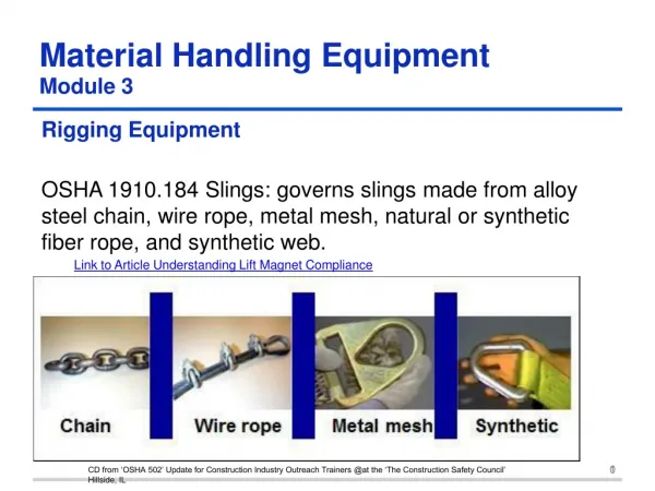
Detailed procedures and specifications for Ground Handling Equipment (GHE) assembly, lifting fixtures, and hardware used in payload integration and shipping. Includes requirements for primary support stands, lifting fixtures, and equipment for safe handling.

E N D
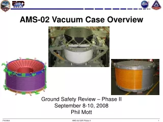
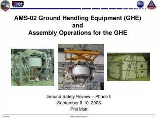
AMS-02 Ground Handling Equipment (GHE) andAssembly Operations for the GHE Ground Safety Review – Phase II September 8-10, 2008 Phil Mott AMS-02 GSR Phase II
KHB 1700.7C Space Shuttle Payload Ground Safety Handbook SW-E-0002E Ground Support Equipment General Design Requirements NASA-STD 8719.9 formerly NSS/GO-1740.9B Standard for Lifting Devices and Equipment Documents Governing GHE Design AMS-02 GSR Phase II
Primary Support Stand (PSS) • Used for payload integration and shipping • Two configurations: Low & High • Constructed with Aluminum 6061 • Covers are Alumalite (painted aluminum face sheet with plastic corrugate) • Factors of Safety • 2 on yield • 3 on ultimate AMS-02 GSR Phase II
Primary Support Stand (PSS) – Low Configuration • Shipping Configuration • 195” x 125” x 117” high • Top Cover is removed as one piece AMS-02 GSR Phase II
Primary Support Stand (PSS) – High Configuration • Assembly/Integration Configuration • 195” x 125” x 166” high AMS-02 GSR Phase II
Primary Lifting Fixture (PLF) • Used to lift the PSS and AMS-02 • Welded steel A36 structure • WLL: 26,800 lbs • Factors of Safety • 3 on yield • 5 on ultimate • Initial proof load to 2X WLL • Annual load test to 1X WLL AMS-02 GSR Phase II
Multi Purpose Lifting Fixture (MPLF) • Used to lift the Lower USS (LUSS) into place on the Upper USS and to lift the PAS into place for attachment • Welded steel A36 structure • WLL: 7000 lbs • Factors of Safety: • 3 on yield • 5 on ultimate • Initial proof load to 2X WLL • Annual load test to 1X WLL AMS-02 GSR Phase II
Lower USS (LUSS) Shipping Fixture • Used to ship/move/install the Lower USS • Can be moved with forklift or crane/MPLF • Welded steel A36 structure AMS-02 GSR Phase II
Other Hardware • Can be moved with forklift, crane, air pallet, hand carts, or by hand • All lifting hardware will meet NASA-STD 8719.9 AMS-02 GSR Phase II
Assembly Operations AMS-02 GSR Phase II
Arrival at KSC – Unload/Prep in the SSPF Airlock • Crane PSS/Upper USS-02. • Fork/Crane Lower USS-02 • Fork/Crane all other Hardware including CGSE AMS-02 GSR Phase II
Arrival at KSC – Unload/Prep in the SSPF Airlock (cont) AMS-02 GSR Phase II
Move Into SSPF – Footprint 7 • Crane or air pallet PSS/USS-02 • Crane, fork, or air pallet all other hardware AMS-02 GSR Phase II
Unpacking • Remove the upper cover from the PSS using the MPLF or slings • Remove the side panels from the PSS • Remove the cover from the LUSS Shipping Fixture • Set up Cryosystem GSE (CGSE) AMS-02 GSR Phase II
PSS Preparation for AMS-02 Assembly/Integration • Install Upper Columns and Beams on the PSS AMS-02 GSR Phase II
PSS Preparation for AMS-02 Assembly/Integration • Raise the PSS/Upper USS-02 to the high position • Install supports AMS-02 GSR Phase II
Installation of the Lower USS onto the Upper USS • Fork the Lower USS under the Upper USS in the PSS AMS-02 GSR Phase II
Installation of the Lower USS onto the Upper USS (cont) • Lift the Lower USS into position using the MPLF • Position hydraulic jacks under the Lower USS for support and final positioning • Attach Lower USS to Upper USS with pins and bolts AMS-02 GSR Phase II
Installation of the PAS • Weight of PAS = 220 lbs • PAS will be installed using the LUSS, overhead crane, and bottle jacks PAS EBCS AMS-02 GSR Phase II
Installation of the PAS (cont) • Procedure similar to Lower USS installation – Details in work • Place PAS on top of LUSS Shipping Fixture • Place under payload using forklift • Raise and rotate using bottle jacks AMS-02 GSR Phase II
Installation of the Keel • Weight of Keel = 67 lbs • Keel will be a 2 person manual lift and bolts installed by a 3rd person AMS-02 GSR Phase II