Download
1 / 42
420 likes | 597 Vues
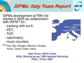
Ljublijana. Trento. Udine. Trieste. Legnaro. IN F N. SIPMs: Italy Team Report. SiPMs development at FBK-irst started in 2005 as collaboration with INFN ( * ) for: - tracking with sci-fi; - PET; - TOF; - calorimetry; - muon counters.

E N D
Ljublijana Trento Udine Trieste Legnaro INFN SIPMs: Italy Team Report SiPMs development at FBK-irst started in 2005 as collaboration with INFN(*)for: - tracking with sci-fi; - PET; - TOF; - calorimetry; - muon counters. (*)Pisa, Bari, Bologna, Messina, Perugia, Roma, Trento,Trieste, Udine Aldo Penzo, INFN-Trieste HCAL Working group, CMS Upgrade Workshop FNAL, 19 Nov 2008
Summary of multiple contributions • http://www.ts.infn.it/eventi/TPDPPC_2008/ • Valter Bonvicini - The INFN R&D FACTOR • Claudio Piemonte - Development of SiPMs at FBK-irst • Arjan Heering - Requirements of SiPMs for CMS HCAL upgrades • Adam Para - Photodectors for dual readout calorimetry: characterization and testing of SiPMT's • Aldo Penzo - Calorimetry R&D in FACTOR • Dalla Torre - Single photon detectors for Cherenkov Imaging • Valter Bonvicini - Preliminary results on SiPM irradiation tests • Giovanni Pauletta - SiPM characterization and applications; past and future test activities at FNAL
FACTOR Project [Walter Bonvicini et al.: Messina, Roma, Trieste, Udine + FBK/irst] • Within FBK/irst - INFN agreement, a (3-year) project (FACTOR) aims at establishing SiPMs as choice devices for (dual) readout of (compensating) hadron calorimeters. • FBK-IRST has long-standing collaboration with INFN in the fields of: • Radiation-hard Si detectors (for SLHC) • use of oxigen-rich substrates: • DOFZ substrates • Cz/MCz substrates (Magnetic Czochralski) • Epitaxial substrates • use of p-type substrates • Integration of Si detectors and (front-end) circuits on the same substrate • 3D detectors
ITC-IRST (Trento) ITC (Now Fondazione Bruno Kessler ) – IRST is a public research and technology Institute, working since 1994 on the development and on the production od semiconductor devices for research and applications. It has a fully equipped Microfabrication Laboratory in which silicon devices are built. - Ion Implanter - Furnaces - Litho (Mask Aligner ) - Dry&Wet Etching - Sputtering &Evaporator - On line inspection - Dicing
TCAD simulation CAD design Device testing Fabrication Activity of SRD group Development and production of Si radiation detectors. Expertise covers the main aspects of the development:
Previous/current products • Double-sided strip detectors: • Area:7.5x4.2cm2 • Orthogonal or inclined strips on 2 sides • DC- or AC-coupled • 700 + 800 “in spec” devices fabricated for AMS and ALICE (2002-2005) • Pixel detectors: • MEDIPIX (thick 1.5mm), 170x170/55x55 mm2 • ALICE (200mm) 400x50 mm2
Ionising track column type n column type p Wafer surface electrons holes Substrate type n 3D Si Detectors (carriers generated along the track are collected almost simoultaneously) • Short distance electrodes n e p: • low depletion voltage • short charge collection distance Electrodes are columns penetrating into the bulk extremely fast and radiation resistant See S. Parker et al., NIM A395 (1997)
metal SEM pictures of 3D devices oxide hole contact n+ diffusion Col. depth 180mm Col. width 10mm 3D Si Detector ProjectFBK-irst and INFN-Trieste (L. Bosisio et al.) • Collaboration for tests: • Ljubljana • UC Santa Cruz • INFN-Genova (ATLAS Pixel) • CERN (ALICE Pixel) • Applications of this technology in other devices: • ‘throughout holes” transfer signals to back face (ex.SiPM) • planar detectors with “active edge’ (ex. imaging X-rays)
Shallow-Junction SiPM guard region n+ p p epi p n+ p+ subst. High field region Drift region SiPM IRST technology • Substrate: p-type epitaxial • 2) Very thin n+ layer • 3) Polysilicon quenching resistance • 4) Anti-reflective coating optimized for l~420nm [C. Piemonte: “A new Silicon Photomultiplier structure for blue light detection” NIMA 568 (2006) 224-232]
Wafer Main block • square SiPMs with area: • - 1x1mm2,2x2mm2 • - 3x3mm2, 4x4mm2 • circular SiPMs • linear arrays of SiPMs: • - 1x8, 1x16, 1x32 • - 4x4 matrix of SiPMs Configuration on Si wafer Second production run First production run (2005)
1x1mm2 2x2mm2 3x3mm2 (3600 cells) 4x4mm2 (6400 cells) Circular: diameter 1.2mm diameter 2.8mm Characteristics of FBK-irst SiPMs Geometries: Fill factor: 40x40mm2 => ~ 40% 50x50mm2 => ~ 50% 100x100mm2 => ~ 76%
C. Piemonte et al. “Characterization of the first prototypes of SiPM fabricated at ITC-irst” IEEE TNS, February 2007 Tests performed at FBK • I-V measurement • fast test to verify functionality and uniformity of the properties • Functional characterization in dark • for a complete characterization of the output signal and noise properties (signal shape, gain, dark count, optical cross-talk, after-pulse) • Photo-detection efficiency
Static characteristic (I-V) Reverse I-V Breakdown current: determined by dark events Breakdown voltage Leakage current:mainly due to surface generation at the micro-diode periphery • Very useful fast test. Gives info about: • - Device functionality • Breakdown voltage • (Dark rate)x(Gain) uniformity • Quenching resistance(from forward I-V) Performed on several thousands of devices at wafer level
Dark signals are exactly equal to photo-generated signals functional measurements in dark give a complete picture of the SiPM functioning Signal properties – NO amplifier Thanks to the large gain it is possible to connect the SiPM directly to the scope SiPM: 1x1mm2 Cell: 50x50mm2 VBIAS SiPM Digital Scope 50W
~ns Pulse gen. Laser SiPM Pulse area = charge histogram collection Signal properties – NO amplifier pedestal. 1p.e. 2 Excellent cell uniformity 3 4 Linear gain 15
VBIAS SiPM Digital Scope 50W Signal properties – with amplifier A voltage amplifier allows an easier characterization, but attention must be paid when determining the gain Pulses at the scope. Av 100x s = single d = double pulses a = after-pulse
Microcell functionality measurements measurements with RWTH, Aachen and Josef Stefan , Ljublijana
Measurement of the microcells with 5mm Pencil LED scan
Gain 16 x Dark Count of 1mm2 SiPM -15C -25C Dark count -25C -15C 4x4mm2 SiPM - 50x50mm2 cell 4x4mm2 Signal shape 1mm2 SiPM
4x4mm2 SiPM - 50x50mm2 cell T=-25C Vbd=27.6V Charge spectra when illuminating the device with short light pulses 2 3 28.6V 1 4 5 • Same conclusions as for • the previous device: • Excellent cell response uniformity • over the entire device (6400 cells) • Width of peaks dominated by • electronic noise 5 6 29.2V 4 3 2 1 6 7 5 29.6V 4 8 3 2 1
Dark counts vs discrim. threshold • Each of the above curves represents the dark count rate as a function of the counting discriminator threshold. • Different curves correspond to different bias voltages. Dark counts were also measured as a function of temperature.
Area efficiency ~ 20% 4V 3.5V PDE=QE*Pt*Ae 3V 2.5V PDE DV=2V QE=quantum eff. Pt=avalanche prob. Ae=area eff. 350 400 450 500 550 600 650 700 750 800 QE vs Wavelength long l: low PDE because low QE short l: low PDE because avalanche triggered by holes Reduced by ARC Reduced by small epi thickness Measured on a diode
HB,HE,HO HF Comparison of PDE • From Arjan in Trieste, 3 June 2008
Activities at Trieste-Udine • The FACTOR collaboration is interested in the development of the device and in its optimization for application to: • Present application interests: • Calorimetry with fiber-based optical readout • Large – area scintillator – based muon counters • Scintillating fiber – based tracking • future space experiments for detection of UHECR • FEL studies and instrumentation • future large – area, ground – based x-ray telescopes • Action Plan: • comparative studies for detailed understanding of device characteristics • Application tests • Optimization of properties as a function of application
First year FACTOR • 2007: mainly dedicated to device characterization and test: • Comparison of SiPM characteristics produced by different manufacturers; • Measurements of SiPM characteristics as a function of T; • Irradiation of the devices and study of radiation damage effects; • Tests with SiPMs coupled to wls fibers for scintillator read-out. • Energy and time resolution measurements; • Study of optimal packaging, electronics placement, etc. • At the moment, we are performing tests on SiPMs from 3 different • sources: • Forimtech (MRS): • 1 mm2 in TO18 - P 560 nm - 556 µcells 43x43 µm2 • Photonique (MRS): • “GR sensitive” - 1 mm2 in TO18 - 556 µcells ~ 43x43 µm2 • “Blue sensitive” - 1 mm2 in TO18 - 556 µcells ~ 43x43 µm2 • “Blue sensitive” - 4.4 mm2 on PCB - 1748 µcells ~ 50x50 µm2 • “Blue enhanced” – 9 mm2 in TO5 – 8100 µcells ~ 33x33 µm2 • IRST (polysilicon), 1 mm2 - P 420 nm (devices from 2nd and 3rd batch) • 625 µcells, 40x40 µm2
Fast Amplifier • Amplifier used for fast characterization of SiPMs: • Agilent ABA-52563 3.5 GHz RFIC Amplifier • (economic, compact, internally 50-Ω matched, gain ~ 20 dB)
Amplifier Characterization • Temperature dependence: • Measurements performed with the DUT in a climatic chamber (with humidity control) • The amplifier was outside the chamber, connected via a special 18 GHz ft 50 cable. • Timing characteristics can be studied
Present Tasks • SiPM Development • Comparative device characterization (ISRT, Hamamatsu, Formitech) • Development (in collaboration with IRST) • Optimization of packaging & (fast!) preamplification • Irradiation studies (so far on 24 SiPM's) • FBK-irst, Hamamatsu Photonique, Formitech • X-rays @ INFN Legnaro Labs (50 – 500 krad) • neutrons @ IJS reactor, Ljubljana (~4.8 x 101 0 n/cm 2 ) • Application Studies • Large area muon counters (FNAL) • Calorimetry with optical readout (FNAL/CERN/Frascati) • Scintillator-based fine-grained hodoscopes (CERN) • Preliminary study of Scint. Strips viewed by IRST SiPM at the FNAL test beam (prototype of muon detector/tail catcher for ILC)
WLS fiber 2.5 cm 6 cm SiPM 6 cm Scint. Tile Test at Frascati Electron beam with a Cherenkov calorimeter counting multiplicity
Test beam at CERN • Test beam at CERN (May/June 2008) with the MICE experiment: 8 extruded scintillator bars (1.5x1.9x19 cm3) with wls fibers, read out by SiPMs (IRST and Hamamatsu), all other bars of the MICE calorimeter read out by MAPMT. • An ad hoc mechanical receptacle was realized to couple and align the fibers with the SiPMs and test them in a 2 GeV positron beam • Frontend electronics: VA64TAP3.1 +LS64 by Gamma Medica-IDEAS; trigger signals sampled by an Altera with a 320 MHz clock
Mice detector • A small fraction of the prototype fibers are readout with SiPM. The SiPM receptacle is visible to the right
The SiPM response Pulse-height plot of the SiPM obtainedselecting good events on the MAPM side • Correlation MAPMT vs SiPM amplitude
Radiation studies • Systematic campaign this year: study resistance to radiation effects of SiPMs produced by different manufacturers • Objective: study both surface and bulk damage in the devices • Types of radiation used: X-rays (up to 50 keV) and neutrons • Measurement strategy: I-V characterization, dark count and gain before and after irradiations, annealing studies • 24 devices from FBK-irst, Photonique (CPTA) and Hamamatsu irradiated so far; further irradiations are foreseen in the next weeks • X-rays: INFN National Laboratories of Legnaro (LNL), X-ray tube (W target), Vmax = 50 kV, dose rate measured with calibrated Si p-i-n diodes • Neutrons: Nuclear Reactor of the Institute Josef Stefan of Ljubljana (Slo), max power ~ 250 kW, very high fluence achievable X-rays @ INFN Legnaro Labs (50, 100 and 150 krad); X-rays @ INFN Legnaro Labs (300 and 500 krad); neutrons @ IJS reactor, Ljubljana (fluence ~ 4.8 x 10¹⁰ n/cm-2);
Irradiation studies (so far on 24 SiPM's) • X-rays @ INFN Legnaro Labs (50 – 500 krad) • neutrons @ IJS reactor, Ljubljana (~4.8 x 10¹⁰ n/cm2) • (spectrum ?) • Very preliminarly: • With 300 krad X-rays, HPK DC increase by 20 – 25 • FBK by 4 - 5 • With 500 krad, HPK by 36-40, FBK by 6 - 8 • With 4.8 x 10¹⁰ n/cm2, HPK DC increase by 45-60, FBK by 15 - 20 . (See next page)
Other measurements and estimates See: T. Matsumura (June 29, 2007) International Workshop on new photon-detectors (PD07) (Kobe University) Neutron ≈ Proton Proton ≈ 100 x X-ray
Magnetic field resistance • “Investigation of a Solid-state Photodetector”, NIM A 545:727-737 (2005). • “Effects of a strong magnetic field on LED, extruded scintillator and MRS photodiode”, NIM A553: 438-447 (2005) • (Vishnu V. Zutshi)
SiPM for HF? • PMT fake signals in HF: show-stopper? • SiPM useful but: • Radiation hard? • Small dimensions? • Dinamic range? • Consider matrix of 4x4 mm2 FBK SiPM • To cover 2.4 cm diameter PMT window ~130 GeV up to few TeV!
SiPM matrix… …if 1 SiPM costs ≤10$ … … not out of question?