Download
1 / 45
460 likes | 505 Vues
Learn about MEF 22, a guide for Carrier Ethernet-based mobile backhaul networks, with detailed specifications and guidelines for equipment manufacturers and service providers.

E N D
Introducing the Specifications of the MEF MEF 22: Mobile Backhaul Implementation Agreement February 2009
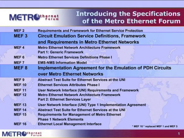
Approved MEF Specifications • MEF 2 Requirements and Framework for Ethernet Service Protection • MEF 3 Circuit Emulation Service Definitions, Framework and Requirements in Metro Ethernet Networks • MEF 4 Metro Ethernet Network Architecture Framework Part 1: Generic Framework • MEF 6.1 Metro Ethernet Services Definitions Phase 2 • MEF 7 EMS-NMS Information Model • MEF 8 Implementation Agreement for the Emulation of PDH Circuits over Metro Ethernet Networks • MEF 9 Abstract Test Suite for Ethernet Services at the UNI • MEF 10.1 Ethernet Services Attributes Phase 2* • MEF 11 User Network Interface (UNI) Requirements and Framework • MEF 12 Metro Ethernet Network Architecture Framework Part 2: Ethernet Services Layer • MEF 13 User Network Interface (UNI) Type 1 Implementation Agreement • MEF 14 Abstract Test Suite for Traffic Management Phase 1 • MEF 15 Requirements for Management of Metro Ethernet Phase 1 Network Elements • MEF 16 Ethernet Local Management Interface • MEF 17 Service OAM Framework and Requirements • MEF 18 Abstract Test Suite for Circuit Emulation Services • MEF 19 Abstract Test Suite for UNI Type 1 • MEF 20 User Network Interface (UNI) Type 2 Implementation Agreement • MEF 21 Abstract Test Suite for UNI Type 2 Part 1: Link OAM • MEF 22 Mobile Backhaul Implementation Agreement * MEF 10 .1 replaces and enhances MEF 10 Ethernet Services Definition Phase 1 and replaced MEF 1 and MEF 5. MEF 6.1 replaced MEF 6.
This Overview Presentation • Purpose: • This presentation is an introduction to MEF 22 • Audience • Equipment manufacturers building devices that will carry mobile backhaul traffic over Carrier Ethernet • Useful for mobile backhaul service providers architecting their systems for Carrier Ethernet • For wire-line service providers architecting their systems for the inclusion of mobile backhaul traffic over Carrier Ethernet • Other Documents • Presentations of the other specifications and an overview of all specifications is available on the MEF web site • Other materials such as white papers and case studies are also available
MEF 22 Overview Presentation Topics • MEF 22 Overview • Objectives • Scope • Implementation phases • Terminology and concepts • MBH IA Specification Sections • Use cases and migration strategy • Services • Classes of service • Service types • Generic interworking function • Synchronization and clock recovery • Synchronization background information • References and related documents
MEF Mobile Backhaul Implementation Agreement RAN BS UNI UNI Carrier Ethernet Network RAN NC UNI RAN BS • Overview • Provides generic specification for Ethernet backhaul architectures for mobile networks (2G, 3G, 4G) • Explains how to apply existing MEF specifications • User-Network Interface requirements • Service Requirements • Service definitions • Clock synchronization forapplication support
About the Specification • The role of the document is to provide guidelines for implementing mobile backhaul network that is based on Carrier Ethernet • The document includes requirement and recommendations for the equipment, architecture & operation of Mobile Backhaul network. • Mobile Backhaul Implementation Agreement is an MEF specification • It provides a set of requirements and guidelines detailing the use of existing MEF standards and other industry standards in a way that best fit mobile backhaul requirements. • The Implementation Agreement aims to describe best practices as a blueprint for a successful implementation of mobile backhaul services.
Scope of the Implementation Agreement • Utilize existing MEF technical specifications with required extensions to interface and service attributes. • Provide requirements for UNI-C and UNI-N beyond those in MEF 13 & MEF 20. • Define requirements for the implementation of Ethernet Services. • Provide requirements for the usages of Link OAM and Service OAM Fault Management. • Use a single Metro Ethernet Network with external interfaces being only UNIs. • Provide high-level requirements for Class of Service. • Define synchronization requirements where possible for packet based synchronization methods that are transparent to the CEN. • Specify functional requirements applicable to legacy mobile technology using the Generic Inter-Working Function (GIWF) interfaces.
Phased Implementation MEF 22 Mobile Backhaul Implementation Agreement Phase 1 was approved as an official MEF Specification in January 2009. • This first phase includes: • EVCs spanning a single MEN (Metro Ethernet Network). • Synchronization is either delivered outside of the Ethernet transport network or using a packet based method that is transparent to the MEN*, e.g. treated as standard Service Frames • GSM, WCDMA, CDMA, CDMA2000, and WiMAX 802.16e. • Subsequent phases are anticipated to include: • EVCs spanning arbitrary number of MENs. • Other synchronization methods. • Other mobile standards, such as LTE (Long Term Evolution). • Synchronous Ethernet • And other topics
Terminology and Concepts (1) • The Specifications and presentations refer to MENs (Metro Ethernet Networks) not Carrier Ethernet Networks. Why is that? • The technical work of the MEF as described in the specifications, together with the work of associated standards bodies, collectively enable the functionality and attributes of Carrier Ethernet • The completed specifications continue to refer to MENs (Metro Ethernet Networks) but this is now a generic term covering the enabled service network in the increasing variety of Access, Metro and long haul networks • Some Specifications refer to CENs (Carrier Ethernet Networks) this term may be used interchangeably with MENs as in this document
Terminology and Concepts (2) • The scope of the “Mobile Backhaul” network as defined for the specification • The Mobile Backhaul is defined as the network between the: • Radio Network Controllers (RNCs), and • Radio Access Networks Base Station (RAN BS). • Mobile Backhaul Implementation Agreement provides guidelines to architecture, equipment & operation to that part of the network
Terminology and Concepts (3) • Network Elements addressed by the Specification Terminology used in the specification and this overview • The RAN CE is a generic term that identifies a mobile network node or site, such as a RAN network Controller or RAN Base Station • A RAN NC may be a single network controller or a site composed of several network elements including: OSS, WCDMA Radio Network Controller or Synchronization Server.
Terminology and Concepts (4) Carrier Ethernet Network RAN BS • The RAN Base Station is shown in the specification as in the diagram on the right • However, this is intended to represent all varieties of configurations typically enclosed and may support several cell towers • A RAN BS may also be a single base station or a collection of several base stations as shown on the right. The actual implementations may integrate the GIWF function, microwave backhaul functions, etc.,
Section Review • Use Cases and Migration Strategy • Four use cases address the migration from legacy networks • Services • This section examines the application of six Carrier Ethernet service types together with the class of service recommendations • Generic Interworking Function • Addresses generic devices to be used as part of the migration strategy • Synchronization and Clock Recovery • Addresses the issues of clock preservation across Carrier Ethernet mobile backhaul networks
Legacy Mobile Backhaul Migration Legacy Network Carrier Ethernet Network Carrier Ethernet Network RAN BS RAN BS Non-Ethernet I/F Non-Ethernet I/F GIWF GIWF UNI UNI UNI UNI GIWF GIWF Non-Ethernet I/F Non-Ethernet I/F RAN NC RAN NC Packet offload over Carrier Ethernet – Use Case 1a Emulation over Carrier Ethernet – Use Case 1b
When RAN nodes are equipped with Ethernet Legacy Network Carrier Ethernet Network Carrier Ethernet Network RAN BS RAN BS UNI UNI UNI UNI RAN NC RAN NC RAN dual stack – Use Case 2a Full Ethernet – Use Case 2b
Migration legacy to Carrier Ethernet Backhaul (1) • The Mobile Backhaul Implementation Agreement covers various steps in the migration phase • It describes two use cases of mobile backhaul networks that are composed of a legacy network and a Carrier Ethernet network in parallel. • The first of these two use cases employs a “Generic Inter-Working Function” to interface between the legacy base station / network controller and the Carrier Ethernet network: Legacy Network Carrier Ethernet Network RAN BS Non-Ethernet I/F GIWF UNI UNI GIWF Non-Ethernet I/F RAN NC
Migration legacy to Carrier Ethernet Backhaul (2) • The second legacy use case describes a hybrid offload model. The network controller and base stations maintain legacy network (TDM, ATM, or HDLC/PPP) connections for voice traffic and native Carrier Ethernet interfaces for data traffic: Legacy Network Carrier Ethernet Network RAN BS UNI UNI RAN NC
MBH Service Requirements Addressed • Carrier Ethernet Services for Mobile Backhaul • Typically there are 1-2 RNC sites and between hundreds to thousands of RAN BS sites • Bandwidth requirements for a base station site will vary and may range from a few Mbps to over a Gbps • Services need to be: • Scalable • Flexible • Cost effective • Generally, the requirement is to follow one of the following MEF services: • Ethernet Private Line Service • Ethernet Virtual Private Line Service • Ethernet Private LAN Service • Ethernet Virtual Private LAN service • Ethernet Private Tree Service • Ethernet Virtual Private Tree Service
Service Definitions – Point-to-Point (E-Line) • Similar to leased lines • Requires traffic separation per RAN BS at RAN NC • The specification cover private and virtual private line cases • EVPL shown here
Service Definitions – Ethernet LAN Service (E-LAN) • Virtual LAN service • Requires traffic separation per RAN BS at RAN NC • The specification cover private and virtual private LAN cases • EP-LAN shown here
Rooted Multipoint (E-Tree Service) • Similar behavior as leased lines • Supports simpler RAN BS and RAN NC solutions • Multiplexing could be used for increased traffic separation • The specification cover private and virtual private routed multipoint services • EVP-Tree shown here
MEF 22 provides service modeling and mapping guidelines Guidelines for the number of CoS classes to use Bundling traffic types into limited number of CoS classes CoS class performance requirements The MBH IA specifies QoS requests to enable service class differentiation The “must” request is to support at least two Class of Service. But the recommended request is to support four Class of Service. Traffic Separation
Mobile Backhaul Generic Interworking Function (1) • The Mobile backhaul GIWF (Generic Interworking Function) • Mobile Backhaul Generic Interworking Function (GIWF) provides adaptation and interconnection between any legacy mobile equipments (TDM/ATM/HDLC based) in the base station and network controller and the Metro Ethernet network at the UNI. • It enables the joint backhaul of any combination of 2G, 2.5G, 3G (legacy based) and Evolved-3G & 4G (Ethernet based) voice and data traffic over a single Carrier Ethernet RAN (Radio Access Network). • The adaptation of the legacy mobile traffic to the Carrier Ethernet service can be based on TDM circuit emulation standards as well as ATM/HDLC pseudo-wire standards.
Mobile Backhaul Generic Interworking Function (2) • How the GIWF handles existing GSM based networks • GSM uses a number of T1 (1.5 Mbit/s) or E1 (2 Mbit/s) circuits to connect the base station with the network controller. • The GIWF terminates a circuit emulation service (CES) per such E1/T1 circuit at the cell site or service edge and at the network controller site • A variety of circuit emulation services can be used in the implementation agreement (MEF8 (CESoE), TDMoMPLS, SAToP, CESoPSN) Service Provider Network TDM Circuit Emulation CES IWF CES IWF TDM Ethernet Ethernet TDM Carrier Ethernet Network RAN NC E-Line Service RAN BS Ethernet UNI Ethernet UNI TDM Base Station demarcation TDM Network Interface CES IWF: Circuit Emulation Interworking Function
Technology Interworking Service Provider Network Carrier Ethernet Network ATM Pseudo-wire CES IWF CES IWF ATM/TDM Ethernet Ethernet ATM/TDM Carrier Ethernet Network RAN NC RAN BS E-Line Service Ethernet UNI Ethernet UNI ATM / TDM Network Interface ATM / TDM BS demarcation • How the GIWF handles existing UMTS / WCDMA networks • These Technologies uses ATM over a number of bundled T1 (1.5 Mbit/s) or E1 (2 Mbit/s) circuits to connect the base station with the network controller. • The GIWF terminates an ATM pseudo-wire or a TDM circuit emulation tunnel at the cell site or service edge and at the network controller site • A variety of ATM pseudo-wire and/or TDM circuit emulation standards can be used in the implementation agreement
Technology Interworking • How MEF 22 aligns with ATM pseudo-wire and TDM circuit emulation solutions? • The MEF has defined MEF 8 for TDM over Ethernet circuit emulation; the specification is maintained by the MEF • The MPLS-based circuit emulation of TDM and ATM circuits is defined by the IP/MPLS Forum. The MEF liaises with the IP/MPLS Forum to ensure the specifications are aligned.
Synchronization • Key Issue • Migration to all packet networks means loss of TDM clock source • Three principal Components of sync • Frequency synchronization(2G, 3G, 3.5G) • Phase synchronization(4G in some cases) • Time of Day synchronization • The following approaches are possible • Outside of the Ethernet transport network (e.g. via GPS) • Packet Based Synch using dedicated packet flow (e.g. IEEE 1588 V2, NTP) or using the clock carried by circuit emulated data (the following methods are possible : Differential Clock Recovery, Adaptive Clock Recovery) • Synchronous Ethernet
MEF Approach to Synchronization • Packet based • Packet based methods are in scope for Phase 1 • Synchronization quality requirements reference the ITU G.8261 standard • The IA is agnostic to specific methods/implementations like adaptive clocking, RTP-extended adaptive clocking, IEEE1588 etc. • Eliminates the cost and need for retention of T1/E1 circuit solely for synchronization • Other approaches • Common Clock (GPS, legacy E1 clocking) is out of scope • Synchronous Ethernet in scope for future phases
Mobile Backhaul SynchronizationBackground Background The following 8 slides are intended to assist the readers understanding of the topic and background concepts behind the implementation agreement
Mobile Backhaul Synchronization Background (1) • Background Information • The following slides are not descriptive of MEF 22 but are intended as useful background knowledge • Relevant ITU Standards for Clock Requirements for Circuit Emulation services • The synchronization requirements are derived from the ITU-T Recommendation G.8261, which studies timing and synchronization over packet based networks and examines the requirements for different mobile technologies. • Subsequent versions of this ITU specify clocks conforming to G.823 (for signals related to the E1-hierarchy) or G.824 (for T1-hierarchy signals) • These standards define the permissible output jitter and wander for two levels • Clock (Jitter and wander) requirements for the traffic interface are defined in ITU-T G.823, Section 5 for E1 and in ITU-T G.824, Section 5, for T1 • Clock (Jitter and wander) requirements for the synchronization interface are defined in ITU-T G.823, Section 6.2.4 for E1 and in ITU-T G.824, section 6.2.2 for T1
Mobile Backhaul Synchronization Background (2) • Principle types of synchronization • There are 3 principal types of synchronization that are of importance: • Frequency synchronization • Relate to the alignment of clocks in frequency, a process that is also referred to as syntonization • Phase synchronization • Imply that the two clocks are aligned in phase, a process that also referred to as relative-time synchronization • Time synchronization • Also referred to as time-of-day synchronization or wall-clock synchronization where the clocks in question are traceable to a common, universal, time-base such as UTC
Mobile Backhaul Synchronization Background (3) • Important synchronization types and requirements in cellular networks (1) • GSM Base Station (frequency synchronization) • Timing requirement applicable to the GSM radio interface can be found in the ETSI technical specification TS 145.010 • The radio interface requirement for a GSM base station is frequency accuracy of ±50 ppb and ±100 ppb (pico BS) • The need for this requirement stems primarily from the need to support handover of mobiles between base stations • UMTS FDD Base Station (frequency synchronization) • The timing requirement applicable to the WCDMA FDD radio interface can be found in the ETSI technical specification TS 125.104 • The radio interface requirement for UMTS FDD base stations is a frequency accuracy of ± 50ppb (wide area), ±100 ppb (local area) and ±250 ppb (Home BS); for the FDD mode there are no phase alignment requirements
Mobile Backhaul Synchronization Background (4) • Important synchronization types and requirements in cellular networks (2) • UMTS TDD Base Station (frequency and phase synchronization) • The timing requirement applicable to the WCDMA TDD radio interface can be found in the ETSI technical specification TS 125.105 • The radio interface requirement for UMTS TDD base stations is a frequency accuracy of ±50 ppb; for the TDD mode there is the additional requirement for the phase alignment of neighboring base stations to within 2.5 µs. • 3GPP2 CDMA2000 Base Station (frequency and time synchronization) • The relevant CDMA2000 standards are the 3GPP2 C.S0010-B and 3GPP2 C S0002-B • According to the CDMA2000 specifications the average frequency difference between the actual CDMA transmit carrier frequency and specified CDMA transmit frequency assignment shall be less than ±50 ppb • The time error should be less than 3μs: due to that it is a common practice to equip CDMA base stations with GPS receivers
Mobile Backhaul Synchronization Background (5) • How network synchronization is achieved for emulated circuits over a packet-based infrastructure (1) • There are 3 major methods: • Network Synchronous Method. • This is supported via a local GPS or via a master –slave synchronization network using the physical layer to distribute the synchronization • Differential clocking mode • A PRC-traceable reference is required at both ends of the packet network. However often a this may not be available for service providers at every possible site, such as a remote cell site • The system will use the PRC-traceable clock source, which is fed into all the elements of the network • The system will use the common clock source as well as observe the time stamps received from the circuit emulation service (CESoE / SAToP / CESoPSN) packets received from the packet network and calculate the differential to recover an accurate clock • This recovered clock reference is then used to transmit the TDM frames
Mobile Backhaul Synchronization Background (6) • How network synchronization is achieved for emulated circuits over a packet-based infrastructure (2) 3. Adaptive Clock Recovery • In some deployments, there is no PRC-traceable reference nor GPS source available at the remote site • The CPE at the cell site has to completely rely on the incoming packet stream from the Ethernet network to calculate the clocking reference • The clock accuracy, thus derived, should be of suitable high quality, sufficient to recover a timing signal compliant to the 3GPP mobile standards (e.g. accuracy of 16 ppb or higher) • The central office will be using a primary clock source reference, and the receiving site will derive the clock based on the incoming circuit emulation service packets
Mobile Backhaul Synchronization Background (7) • The requirements from Clock Recovery over PSN based MBH • Any clock recovery over packet mechanism should be designedprimarily to meet the clock synchronization requirements for GSMand UMTS RANs as specified in ETSI EN 300 912 and TS 125 402 "Synchronization in UTRAN stage 2” • Jitter and wander measured at the output of the GIWF TDM-bound interface should meet the traffic interface requirements specified in ITU-T recommendations (G.823/G.824/G.825) • The wander budget allocated to the MEN and the GIWF as measured at the output of the GIWF TDM-bound interface should meet the traffic interface requirements of ITU-T G.8261, Deployment Case 2 • Frequency accuracy in holdover should conform to a standard Clock as applicable • A robust clock recovery mechanism should also maintain itsoutstanding performance even under the most demanding network conditions, such as high Packet Delay Variation (jitter) and packetloss ratio
Mobile Backhaul Synchronization Background (8) • How clock recovery solutions are related to 1588v2 and NTP • IEEE 1588v2 and NTP (Network Time Protocol) define how to transport time information over the network • The algorithms to reconstruct and recover the clock are vendor specific • This is an "implementation" issue rather protocol • 1588v2 implementation actually calls for a standardized implementation of the information carried while maintaining the high clock accuracy currently achieved through clock recovery implementations • The clock recovery implementations should interoperable and complement 1588v2 standard. • The clock recovery implementations should comply with G.823, G.824, G.8261, G.8264, G.8265 and G.8266 as applicable
MEF 22 Reference Works • Other MEF documents on which parts of the Mobile Backhaul Implementation Agreement are based • The services and requirements that appear at the Mobile Backhaul Implementation Agreement doc are based on: • The services defined in MEF 6.1 Ethernet Service Definition – Phase 2 • The attributes defined in MEF 10.1 Ethernet Service Attributes – Phase 2 • MEF 13 & MEF 20 (UNI Types 1 & 2) • Other documents currently under development by the MEF Technical Committee (Ethernet Classes of Service, Service-OAM and External Network-to-Network Interface technical specifications) • It is highly recommended to be familiar with the requirements in the above two documents before reading the Mobile Backhaul Implementation Agreement document. These are available on the MEF Public web site Information Center
Final Word • Next Actions • Read the detailed MEF 20 Implementation Agreement available on the MEF web site • Further information related to implementation is to be found on the MEF site: • Further Technical FAQs beyond the scope of this document • A full reference presentation with additional market perspectives • White papers, case studies, applications • Video presentations
End of MEF 22 Overview More information: www.metroethernetforum.org