Download
1 / 47
470 likes | 751 Vues
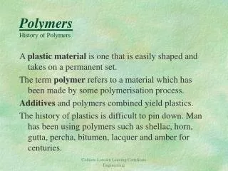
Applications of Polymers in Nanotech/Nanofab Polymers are at the forefront of many current approaches to nanofabrication, so we will whiz through a quick overview of some of the currently investigated approaches to fabrication 10 — 100nm

E N D
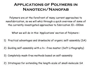
Applications of Polymers in Nanotech/Nanofab • Polymers are at the forefront of many current approaches to nanofabrication, so we will whiz through a quick overview of some of the currently investigated approaches to fabrication 10—100nm • What we will do in this ‘Applications’ section of Polymers : • 1) Practical advantages and drawbacks of organic self-assembly (SA) • Guiding self-assembly with a h -free master (Soft Lithography) • Completely mask-free methods based on self-assembly • Strategies for extending the length-scale of small-molecule SA
Bottom Up Fabrication • Challenges of Traditional Mask Lithography using Photons: • 1) Inherent diffraction limit (strategies: lower wavelength, near field) • 2) Thermodynamic instability (strategies: ultra-clean fab environment $) • 3) Large number of steps (strategies: highly parallel fabrication $$)
Bottom Up Fabrication • Advantages of Self-Assembled Organics to Control / Exploit: • 1) Small natural size-scale (challenge: too small in many cases) • Thermodynamic minimum (challenge: if so, then usually reversible) • Steps sequential (challenge: control over final state of assembly) • The key difference between • ‘top down’ and ‘bottom up’ : existing desired designed pieces structure pieces Self-assembly engineering
Bottom Up Fabrication The Motif of Self-Assembly Approaches Summarized: To exploit natural and existing mechanisms of structure formation by supplying cleverly-designed starting materials to a system, and then allowing that system to proceed to a thermodynamic equilibrium with desired product as the end result. Demonstration of principle: Assembly of a simple, functioning 12-component electronic logic device by stirring a large array of components in aqueous solution for 1 minute George Whitesides, Harvard University
Bottom Up Fabrication The 2 fundamental general problems to overcome with self-assembly: #1) Natural methods assemble controlled structures on a LOCAL frame of reference at the meso sizescale. We usually want structures indexed to a GLOBAL reference, with LONG-RANGE order and control. #2) In order to exploit the process, we have to understand the process There are two basic approaches to solve #1: A) Guide the patterning process mechanically (physically) using masters B) Guide the patterning optically (non-contact, external) using light
Soft Lithography • A) Guiding a pattern mechanically (physically) using a master: • A traditional photo-lithograpic pattern is used in JUST 1 STEP, then polymer self-assembly for the rest of the process, for defect tolerance, fabrication ease, parallel processing, and small sizescale: • Some representative methods of ‘Soft Lithography’ (photo free) • Replica Molding (to make n copies from 1 photo-lith master) • Micro-Contact Printing (pattern transfer by direct contact) • Micro-molding (using fluid dynamics to form structure in situ) • Soft Lithography is based on elastomeric polymers which can transfer a pattern from a master to a large number of copies, for 1 layer fab.
Replica Molding (REM) Standard photolithography is used to produce a master on Si from a mask A monomer, oligomer, or other pre-polymer (or polymer solution) is poured over the mask to conform to features The resulting polymer needs a Tg below processing temperature (such as PDMS) after curing by heat or UV light The elastomeric PDMS is removed from the original, leaving no residue and holding the negative of the surface
Replica Molding (REM) The original master can be used many times, with PDMS poured and peeled off repeatedly, with good stability This PDMS negative can then act as mask to reproduce the original, with a high Tg polymer such as poly(methyl methacrylate) PMMA, or polyurethane
Replica Molding (REM) The elastomeric properties of the PDMS can also be used to stretch or compress the sizescale, from 180nm of a waveguide to 40nm (Xia, U. Wash.) The drawbacks of this compression are introducing more fabrication steps (reproducible compression limit ~25%) also liftoff surface energies in small systems can exceed the PDMS surface energy (~22 dyn/cm), which increases wear, limiting number of reproductions
Replica Molding (REM) One clever side application however is to use slight expansion and compression for mechanically switchable elastic optical applications Here, optical elements are formed INSIDE the PDMS using liquid metals (Hg or Ga) which conform to the cavity and act as adaptive optics for beam steering and focus
Micro Contact Printing (CP) The PDMS masks can also be applied as flexible stamps, inked with adsorbing or assembling molecules, and then used as small rubber contact stamps The chemical ink covers all surfaces, but Surface relief patterns transfer only molecules in direct contact. 5nm is sufficient, with 200nm spaces. Inks can be adsorbing polymers, reactant compounds, or self assembling monolayers based on silanes or thiols
Micro Contact Printing (CP) Alkane thiols with tailored headgroups provide versatile and powerful chemical control over subsequent patterning, such as polymer adsorption, photoresists, vapour deposition of inorganics, etching, electroplating of metals… PDMS Stamps can deposit controlled patterns within 10nm over many square cm, and have been demonstrated for features down to 35nm (etching of grooves on gold)
Micro Contact Printing (CP) Complex architectures are possible from any master, as long as it’s limited to a single layer to be deposited on a Au or Si coated flat surface The Limitation: This produces one layer well, but only a single layer.
CURVED surfaces are also amenable to micro-contact printing, opening the way to the third dimension through unfolding complex topologies
Micro Contact Molding Here, liquid pre-polymer flows into channels by capilliary action, hardens over time, and with mask removal the desired structures are left behind
Bottom Up Fabrication The result ? : The timescale to produce new design nanostructures has gone from ~6 months to less than 24h, and now much can even be done with a standard inkjet printer (but we still need a mask at some step)
Mask-Free Fabrication Deposition of a trail of liquid from an AFM tip represents a small ink pen
Light to define Patterns using a locally-defined polymerization by a free-space 2-photon process
2PP in x, y, z define a 3D Solid 2PP with IR pulses, (materials are transparent), for UV photo-polymerization Optics can move focal point around quickly in x, y, x from coded model Liquid monomer quickly solidified, rest washed away, object remains.
2pp Photo-Polymerization acrylate monomer is mixed with AIBN initiator, and undergoes photo free radical polymerization locally, by a deep red 2 photon process 2 microns
POLYMERS for OPTICS, ELECTRO-OPTICS, & PHOTONICS Polymeric materials for optics, electro-optics, and photonics can be classified usefully according to their application, as: 1) PASSIVE MATERIALS: where the polymer serves as a benign host for information transmission and ROM storage (for eg: optical fibres, waveguides, and cladding layers) 2) ACTIVE MATERIALS: where the polymer is tailored to respond quickly to electric or optical fields for switching (for eg: high-speed read/write storage, optical routing)
POLYMERS for OPTICS, ELECTRO-OPTICS, & PHOTONICS For either application, our design and synthesis goals are the same—to produce polymers which are efficient and effective: –easy and cheap to synthesize, characterize, and process. –versatile so that properties can be tuned and optimized. –compatible with surfaces and interfaces of existing devices –stable over time, temperature, and a range of environments Optics is the guiding and control of light properties using materials. Electro-Optics isusing materials to mediate the communication between electrons and photons, or using E fields to control optical properties Photonics is the processing and conveying of information using photons instead of electrons. ie: electronics substituting the electrons.
Question 1) Why Photonics? (what’s wrong with electronics ?) • Traditional electronics successfully • Mergedthe conductance of metals • with the inorganic electric transistor • to produce a nearly perfect • communications processing platform • e–copper wiree– • electrons in; electrons out (+ some heat), and one at a time. • It’s the heat and the one-at-a-time parts which can cause problems.
Question 1) Why Photonics? (what’s better about photonics ?) Photonics, in contrast, uses photons the same way, exploiting the advantages of many more ‘coding variables’, low heat loss in a material, and superimposability hνtransparent material distinguishable photons in; distinguishable photons out, with little heat, no cross-talk, and a vast new set of architectures available. Variables include wavelength and polarization state.
PASSIVE optical materials can be either shortpath (~mm), or long path (~km) distances. The polymer properties required for each are much different. Centimetre Millimetre Micrometre Short Path materials are primarily for on-chip signal transport, and require the ability to be patterned somehow, and be stable to temperature and over time once placed
Long Path PASSIVE materials (optical fibres) rely on the same principle of total internal reflection, but now the main concern is the absorptive material losses over long distances, and the mode of propagation For confinement of light in dimensions similar to that of the wavelength, there are only certain allowed quantum solutions to the propagation of the wave through the fibre, called MODES. 0, 1, 2, 3 …
Amorphous polymers have an advantage of flexibility (so that they can be larger diameter when bending), processability, and durability. The main challenge to be overcome is the interaction between organic bonds and the light being transmitted The ability of polymers to be molecularly tailored then allows us to address this problem synthetically, in the fume hood, an approach that would be prohibitively difficult with inorganic glasses. Some of the best waveguiding materials are acrylates such as PMMA. Low loss is a function of few interfaces, and low electronic absorbance.
Transparency ‘windows’ are governed by the energy of the bonds : molecular rotations 0.01 kJ/mol molecular vibrations 10 kJ/mol molecular excitations 1000 kJ/mol The main absorptive losses in amorphous materials stem not from scattering from interfaces/impurities (as with inorganics), but from weak electronic excitations in the C–C, C=O, C–O, and C–H bonds.
Even the best window available however, at (1.54 microns), for PMMA still adds up significantly with path lengths of many km A Synthetic Strategy? Try and minimize the contributions of the vibrational mode excitation, by lowering the bond energy Ross and L. Newsome, Macromolecules 1996, 29, 2374. optical loss = 0.43 dB/km = 0.31 dB/km
The second main concern with passive long path optical fibres is the MODE of light propagation through the material — the solution to the usual quantum mechanical confinement problem there is a natural spread of ‘arrival times’ at the other end, between paths with more reflections, and paths with fewer. This means that light of the same wavelength which departs at the same instant (but propagating with different modes), arrives in a distribution.
This Mode propagation distribution means that there is a natural spread of ‘arrival times’ at the other end, between paths with more reflections, and paths with fewer, which interferes with pulse-coded communication: The result is an unwanted broadening of the once-sharp signal. A synthetic solution is again proposed, based on an optical ‘trick’ that isimpossible to apply to inorganics, but possible with polymers:
In contrast to step-index fibres, we can keep the propagation of various input angle photons ‘in step’ by bending the light through a refractive index that is GRADED across the fibre : Y. Koike, Applied Optics1996, 35, 28. Nice theory, but is it practical to make? A clever and elegant solution was proposed for synthesis of copolymers from different index-of-refraction monomers, using different reactivity ratios between mers.
B A A A B B A B A A B B B B One starts with a hollow PMMA tube, whichis filled with the monomers mA and mB,which have higher and lower n valuesrespectively. Polymerization is carriedout by a UV lamp through the PMMA shell. A and B co-monomers are further tailoredso that the two reactivity ratios aredissimilar, which leads to increasedincorporation of A near the tube wallswhere the photo-initiation light is strongest As monomer A gets used up near the outeredges of the tube, monomer B (with thelower refractive index) is incorporatedin a higher proportion in the middle of thetube, towards the end of the reaction.
The Graded Index Polymer Fibres can then Mode Match efficiently, and travel of many hundreds of km is possible retaining resolvability. STEP index GRADED index
ACTIVE MATERIALScan be classified by what is used to produce optical changes (electrons or other photons), and whether these changes are reversible (for use as re-writable storage) or irreversible (WORM) Electrical-Optical (EO) switching allows information coded as electron packets to be transferred without error to packets of photons Photons Electrons Thus, we need a material which can change it’s optical properties VERY quickly (nanoseconds) and repeatedly (1016), by an electrical signal. PHOTOSWITCHS change their physical properties reversibly with light
Simple mimics of retinal in rhodopsin is azobenzene, spiropyran, DTE, or PNQ embedded in a self-assembled polyelectrolyte structure. The Azo chromophore is best, as it can be switched quickly, reversibly, and repeatedly with high quantum yield.
Azobenzene chromophores can be doped into polymers (cheaper), but this causes dispersion, stability problems due to crystallization and phase segregation over time. Much better to incorporate directly: The two different forms of azobenzene polymers can exhibit very different optical and physical properties, and can be switched with light on the picosecond timescale. The cis form is unstable however, and always reverts back to the trans form, sooner or later.
Optical Information Storage: a) Write Once, Read Many times (WORM) Not much elegance required, just a polymer layer that can change optical properties very quickly and significantly to another state that’s stable. ‘Burning’ a CD is a fair description, with a thin polycarbonate layer on aluminum locally melted by a focused writing laser to make a bit The focusing optics and heat diffusion rates limit the size of these bits to approx: 0.7 microns x 4 microns, with 1.6 microns between tracks.
With each total bit area 1.3x10⁻⁶mm2 = 800,000bits per square mm, or at 8bits per byte = 100,000 bytes/mm2. With a total available disk area of ~ 14 square inches, = 9000mm2, the number of bytes/mm2 times the size in mm2 gives an estimate of the total capacity of a CD: 100kb/mm2x9000mm2 = 900,0000 kb = 900 Mb(megabytes). (theoretical maximum) There is much space used for checking the information however, and other forms of software ‘overhead’, so available space only = ~650 Mb We don’t need much in the way of polymer science for this however…
What IS really tricky is ACTIVE MATERIALS which are reversible. b) Reversible Optical Storage, for re-writable compact disks Here, we DO need to make clever use of polymer properties to allow a photoswitchable property to be fast and significant, but also reversible. How quickly ? Our 650 Mb CD has 5,200,000,000 bits. To write a CD in a minute is ~0.00000007 seconds/bit = 10 nanosec/bit. In principle, a photoswitch like azobenzene would work. In practice, the cis isomer is not stable enough at room temperature (or more). (but there are certain apps)
What one CAN do however is to take advantage of a variation of this optical storage, to re-align the azo chromophores to write localized and reversible birefringence, with all azobenzene groups in the trans state With a full cycle transcis trans now, orientation of trans is used to encode information, not the two isomers. Using polarized light (linear or circular), random vs. oriented bits can be written, erased, and re-read. (whole circuits too) linear light circular light