Download
1 / 17
410 likes | 1.62k Vues
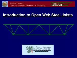
Introduction to Open Web Steel Joists. Background Information. Pre-fabricated “Truss” Type Members Floor and Roof Support Systems Metal Decking Lightly Loaded, Large Open Spaces Warehouses, Wal-Mart, Sam’s Club Very Efficient Structural Members

E N D
Background Information • Pre-fabricated “Truss” Type Members • Floor and Roof Support Systems • Metal Decking • Lightly Loaded, Large Open Spaces • Warehouses, Wal-Mart, Sam’s Club • Very Efficient Structural Members • 1923 – First Joist; Warren Truss Configuration • Round Bars for Chords and Web “Bar Joist”
Interior Web (typ) Top Chord Exterior Web (typ.) Bottom Chord Critical Web Member (typ.)
Background Information • 1928 – Steel Joist Institute (SJI) Formed • First Standard Design Specification Published • 3 Standard Joist Types • Open Web Steel Joists (K-Series); Spans up to 60 ft. • Long-span Steel Joists (LH-Series); Spans up to 96 ft. • Deep Long-span Steel Joists (DLH- Series); Spans up to 144 ft. • Designed as a Truss • i.e. Assumed Pin-Connected Members (k = 1.0) • Continuously Braced by Floor/Roof Deck Against Lateral Buckling
Background Information (SMI Joist Manual) • Design Manual based off of SJI specifications • Incorporates Details, Fire Ratings, Design Procedures, and Load Tables • Load Tables based on ASD Design Methodology: Service Load Design (No Load Factors Applied) • Example: K-Series Joist - 30 ft Span, Max Joist Depth = 20 inches - DL = 120 #/ft, LL = 250 #/ft, Wtot = 370 #/ft - 20k9
Background Information • Steel Joist Institute Requires Web Members to be Symmetric with Center Line of Joist or else they must be Designed as Beam Columns • Angles for Web Members – Angles Must be Crimped • Crimping Creates Symmetry of Web Members with Center Line of Joist • Symmetry Reduces Effects of Bending Stresses due to Eccentric Loading • Design • Chords : Fy = 50 ksi Webs : Fy = 36 or 50 ksi • Verify F.O.S = 1.65 for Critical Web Member
Villanova/SMI Joist Research Partnership • SMI Joist (Hope, AR) • Sole Joist Manufacturer for Wal-Mart, Auto Zone • Study Behavioral Aspects of K-Series Open Web Steel Joists • First Study: 1” x 1” x 1/8” Web Members Crimped and Un-Crimped (Full-Scale and Component Samples) • Second Study: 1” x 1” x 1/8” Web Members Full-Crimped (Full-Scale and Component Samples)
Research Objectives • Evaluate Joist Strength as a Function of Web Member Type • Full-Crimped Single Angle • Crimped Single Angle • Un-Crimped Single Angle • Cold Formed Channel • Define Boundary Conditions for Load and Support of Critical Web Member • Develop Appropriate Strength Model for the Critical Web Member • Develop Flexural Stiffness Model for Predicting Deflections • Recommend Appropriate Adjustments to Existing Joist Design Methodologies Related to Strength and Stiffness
1.0” Top or Bottom Chord 1.0” 0.5” 0.29” 0.5” 0.5” 0.21” Location of Applied Load Web Member 1” CL Joist and CG Web Assumed Location of Applied Load CL Joist b.) Crimped a.) Un-Crimped Web Member Cross Sections (Stage 1) • Un-Crimped Web Angle • Analyzed as a Beam-Column (Axial Force and Bending Moment) • Crimped Web Angle • Analyzed as Column (Axial Force Only)
Top or Bottom Chord 1.0” 1.0” 0.5” Location of Applied Load 0.5” Web Member 1.0” CL Joist and CG Web a.) Full-Crimped b.) Cold-Form Channel Web Member Cross Sections (Stage 2) • Full-Crimped Web Angle • Analyzed as a Column • Cold-Form Channel • Analyzed as a Column
Frame Model (Fixed System) Connections are Rotationally Restrained Truss Model (Pinned System) Connections are Rotationally Free Design Models
Lab Sample Tests Non-standard joist
Laboratory Objective • Investigate strength of top chord for two conditions • chord with out wood nailer • chord with wood nailer • Look at strength using measured data and analytically using column analysis.
Top Chord Analysis • Compare measured force in top chord with design capacity • Measured force determined from truss analysis
Design Capacity • Design Capacity Based on Column AnalysisModel Assumes pinned Connections at JointsSteel Strength is 50 ksi
Publications • “Strength and Design of Open Web Steel Joists with Crimped-End Web Members,” ASCE Journal of Structural Engineering, accepted for publication, February 2002. Authors: Dr. Yost, Dr Dinehart, Dr. Gross, and Brian Gargan Acknowledgements • SMIJOISTCOMPANY for Their Continuing Support