Designing Cisco Borderless Networks: Advantages, Principles & Hierarchical Models
610 likes | 634 Vues
This chapter delves into LAN design considerations, converged network elements, and Cisco Borderless Networks. Explore the benefits, principles, and hierarchical models of Cisco campus network designs for scalable, reliable, and efficient network infrastructure.

Designing Cisco Borderless Networks: Advantages, Principles & Hierarchical Models
E N D
Presentation Transcript
Chapter 4Switched Networks CIS 82 Routing Protocols and Concepts Rick Graziani Cabrillo College graziani@cabrillo.edu Version 6
Chapter 4 - Sections & Objectives • 4.1 LAN Design • Explain how switched networks support small to medium-sized businesses. • Explain how data, voice, and video are converged in a switched network. • Describe a switched network in a small to medium-sized business. • 4.2 The Switched Environment • Explain how Layer 2 switches forward data in a small to medium-sized LAN. • Explain how frames are forwarded in a switched network. • Compare a collision domain to a broadcast domain.
Growing Complexity of Networks Next-generation networks need to: • Be secure, reliable, and highly available • Support a globalized workforce • Integrate legacy devices
Elements of a Converged Network • Converged network solutions integrate: • voice systems • IP phones • voice gateways • video support • video conferencing • Primary benefit of the converged network - just one physical network to install and manage.
Multiple Networks • Different services on different networks.
Converged Networks • Different services on the same network.
Cisco Borderless Networks • The Cisco Borderless Network has the following features: • Allows organizations to connect anyone, anywhere, anytime, on any device; securely, reliably, and seamlessly.
Cisco Borderless Networks • Provides the framework to unify wired and wireless access including: • policy-based networking • access control • performance management across many different device types • Provides network services, and user and endpoint services that are all managed by an integrated management solution.
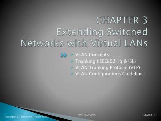
Hierarchy in the Borderless Switched Network • Borderless switched network design guidelines are based on the following principles: • Hierarchical - Facilitates understanding the role of each device at every tier. • Modularity - Allows seamless network expansion and integrated services. • Resiliency – Provides an always available network. • Flexibility - Allows intelligent traffic load sharing. • The three tiers of the hierarchical model are Access, Distribution and Core layers.
Switching • A campus network describes the portion of an enterprise infrastructure that interconnects end devices to services such as intranet resources(residing in the data center) or the Internet. • End devices: computers, laptops, and wireless access points • Intranet resources: web pages, call center applications, file and print services, etc.
Flat Networks • Network were first implemented in a “flat” manner where all PCs, servers, and printers are connected to each other using Layer 2 switches. • No subnets for any design purposes. • All devices in the same broadcast domain. • Broadcast packets received by an end device wastes available bandwidth and resources. • This is not significant with a few devices. • However, this is a significant waste of resources and bandwidth in large networks.
Hierarchical Design • Access layer: Grant the user access to network applications and functions. • Distribution layer: Aggregates the access layer switches wiring closets, floors, or other physical domain by leveraging module or Layer 3 switches. • Core layer (backbone): High-speed backbone, which is designed to switch packets as fast as possible. • Routing capabilities (also at distribution) • High level of availability and adapt to changes quickly • It also provides for dynamic scalability
Hierarchical Model • Scalable networks are implemented in a hierarchical manner. • A hierarchical model has the following advantages: • Provides modularity • Increases flexibility • Eases growth and scalability • Provides for network predictability • Reduces troubleshooting complexity
Cisco Campus Designs • This model provides a modular framework that enables flexibility in network design and facilitates implementation and troubleshooting. • Each layer can be focused on specific functions. • The Cisco Campus Architecture fundamentally divides networks or their modular blocks into the following hierarchical layers: • Building Core Layer: • High-speed campus backbone designed to switch packets fast. • Provides high availability and adapts quickly to changes. • Building Distribution Layer: • Aggregates wiring closets and use switches to segment workgroups and isolate network problems • Building Access Layer: • Grant user access to network devices.
Access Layer • The access layer is dedicated to meeting the functions of end-device connectivity. • Connects a wide variety of devices including Layer 2 switches (e.g. Catalyst 2960) connecting workstations, servers, printers, APs, cameras, …. • The access layer is a feature-rich section of the campus network because it is a best practice to apply features (VoIP, PoE, etc.) as close to the edge as possible.
Access Layer Capabilities – What we want(Not necessarily implemented at the access layer)
Distribution Layer • The distribution layer acts as a service and control boundary between the access and core layers. • It consolidates the wiring closets using switches to segment workgroups and isolate network problems in a campus environment.
Distribution Layer • Acts as a services and control boundary between the access layer and the core. • Access layer and the core are dedicated special-purpose layers. • Access layer - Meets the functions of end-device connectivity • Core layer – Provides nonstop connectivity across the entire campus network. • Distribution layer - Serves multiple purposes.
Distribution Layer Summary • When Layer 3 routing is not configured in the access layer, distribution layer: • Provides high availability and equal-cost load sharing by interconnecting the core and access layer via at least dual paths • Generally terminates a Layer 2 domain of a VLAN (subnet) • Routes traffic from terminated VLANs to other VLANs and to the core • Summarizes access layer routes • Implements policy-based connectivity such as traffic filtering, QoS, and security • Provides for an FHRP
Core Layer • Backbone for campus connectivity • High level of redundancy and adapt to changes quickly • Event of the failure of any component (switch, supervisor, line card, or fiber interconnect, power, and so on) • Permit the occasional, but necessary, hardware and software upgrade or change • Minimal control plane configuration
Core Layer • Backbone (core) that binds together all the elements of the campus architecture to include the WAN, the data center, etc. • Core layer interconnects with a data center and edge distribution module to interconnect WAN, remote access, and the Internet. • The network module operates out of band from the network but is still a critical component.
Core Layer Summary • Provides interconnectivity to the data center, the WAN, and other remote networks • High availability, resiliency, and the ability to make software and hardware upgrades without interruption • Designed without direct connectivity to servers, PCs, access points, and so on • Requires core routing capability • Architected for future growth and scalability • Leverages Cisco platforms that support hardware redundancy
Role of Switched Networks • A hierarchical switched LAN allows more flexibility, traffic management, and additional features: • Quality of service • Additional security • Support for wireless networking and connectivity • Support for new technologies.
Form Factors Stackable Configuration Fixed Configuration • Considerations when selecting switches: • Cost • Port Density • Power • Reliability • Port Speed • Frame buffers • Scalability Modular Configuration
Frame ForwardingSwitching as a General Concept in Networking and Telecommunications • A LAN switch makes decisions based on two criteria: • Ingress port - where a frame enters the device • Destination address • A LAN switch maintains a table that it uses to determine how to forward traffic. • In the diagram, If a message enters switch port 1 with a destination address of EA, then the switch forwards the traffic out port 4. • Layer 2 Ethernet switches forward frames based on the destination MAC address.
Frame ForwardingVideo Demonstration - MAC Address Tables on Connected Switches • The video explains how a switch builds its MAC address table by recording the MAC address of each device connected to each of its ports.
S1 MAC Address Table S2 MAC Address Table Port Port MAC Address MAC Address Internet Router 3 4 2 1 3 4 2 S1 1 S2 1 2 MAC 00-0D B C A MAC 00-0B MAC 00-0A MAC 00-0C Destination MAC 00-0B Source MAC 00-0A FCS Type Data
S1 MAC Address Table S2 MAC Address Table Port Port MAC Address MAC Address Internet 00-0A 1 Router 3 4 2 1 3 4 2 S1 1 S2 1 2 MAC 00-0D B C A MAC 00-0B MAC 00-0A MAC 00-0C Destination MAC 00-0B Source MAC 00-0A FCS Type Data
S1 MAC Address Table S2 MAC Address Table Port Port MAC Address MAC Address Internet 00-0A 1 Router 3 4 2 1 3 4 2 S1 1 S2 1 2 MAC 00-0D B C A MAC 00-0B MAC 00-0A MAC 00-0C Destination MAC 00-0B Source MAC 00-0A FCS Type Data
S1 MAC Address Table S2 MAC Address Table Port Port MAC Address MAC Address Internet 00-0A 1 Router 3 4 2 1 3 4 2 S1 1 S2 1 2 MAC 00-0D B C A MAC 00-0B MAC 00-0A MAC 00-0C Destination MAC 00-0B Source MAC 00-0A FCS Type Data
S1 MAC Address Table S2 MAC Address Table Port Port MAC Address MAC Address Internet 1 00-0A 00-0A 1 Router 3 4 2 1 3 4 2 S1 1 S2 1 2 MAC 00-0D B C A MAC 00-0B MAC 00-0A MAC 00-0C Destination MAC 00-0B Source MAC 00-0A FCS Type Data
S1 MAC Address Table S2 MAC Address Table Port Port MAC Address MAC Address Internet 1 00-0A 00-0A 1 Router 3 4 2 1 3 4 2 S1 1 S2 1 2 MAC 00-0D B C A MAC 00-0B MAC 00-0A MAC 00-0C Destination MAC 00-0B Source MAC 00-0A FCS Type Data
S1 MAC Address Table S2 MAC Address Table Port Port MAC Address MAC Address Internet 1 00-0A 00-0A 1 Router 3 4 2 1 3 4 2 S1 1 S2 1 2 X MAC 00-0D C B A X MAC 00-0B MAC 00-0A MAC 00-0C Destination MAC 00-0B Source MAC 00-0A FCS Type Data
S1 MAC Address Table S2 MAC Address Table Port Port MAC Address MAC Address Internet 1 00-0A 00-0A 1 Router 3 4 2 1 3 4 2 S1 1 S2 1 2 MAC 00-0D B C A MAC 00-0B MAC 00-0A MAC 00-0C Destination MAC 00-0A Source MAC 00-0B FCS Type Data
S1 MAC Address Table S2 MAC Address Table Port Port MAC Address MAC Address Internet 1 00-0A 00-0A 1 00-0B 3 Router 3 4 2 1 3 4 2 S1 1 S2 1 2 MAC 00-0D B C A MAC 00-0B MAC 00-0A MAC 00-0C Destination MAC 00-0A Source MAC 00-0B FCS Type Data
S1 MAC Address Table S2 MAC Address Table Port Port MAC Address MAC Address Internet 1 00-0A 00-0A 1 00-0B 3 Router 3 4 2 1 3 4 2 S1 1 S2 1 2 MAC 00-0D B C A MAC 00-0B MAC 00-0A MAC 00-0C Destination MAC 00-0A Source MAC 00-0B FCS Type Data
S1 MAC Address Table S2 MAC Address Table Port Port MAC Address MAC Address 1 00-0A 00-0A 1 00-0B 3 Internet Router 3 4 2 1 3 4 2 S1 1 S2 1 2 MAC 00-0D C B A MAC 00-0B MAC 00-0A MAC 00-0C Destination MAC 00-0D Source MAC 00-0A FCS Type Data Destination IP address on a remote network
S1 MAC Address Table S2 MAC Address Table Port Port MAC Address MAC Address 1 00-0A 00-0A 1 00-0B 3 Internet Router 3 4 2 1 3 4 2 S1 1 S2 1 2 MAC 00-0D C B A MAC 00-0B MAC 00-0A MAC 00-0C Destination MAC 00-0D Source MAC 00-0A FCS Type Data Destination IP address on a remote network
S1 MAC Address Table S2 MAC Address Table Port Port MAC Address MAC Address 1 00-0A 00-0A 1 00-0B 3 Internet Router 3 4 2 1 3 4 2 S1 1 S2 1 2 MAC 00-0D C B A MAC 00-0B MAC 00-0A MAC 00-0C Destination MAC 00-0D Source MAC 00-0A FCS Type Data Destination IP address on a remote network
S1 MAC Address Table S2 MAC Address Table Port Port MAC Address MAC Address 1 00-0A 00-0A 1 00-0B 3 Internet Router 3 4 2 1 3 4 2 S1 1 S2 1 2 MAC 00-0D X C B A MAC 00-0B MAC 00-0A MAC 00-0C Destination MAC 00-0D Source MAC 00-0A FCS Type Data Destination IP address on a remote network
S1 MAC Address Table S2 MAC Address Table Port Port MAC Address MAC Address 1 00-0A 00-0A 1 00-0B 3 Internet Router 3 4 2 1 3 4 2 S1 1 S2 1 2 MAC 00-0D X C B A MAC 00-0B MAC 00-0A MAC 00-0C Destination MAC 00-0D Source MAC 00-0A FCS Type Data Destination IP address on a remote network
S1 MAC Address Table S2 MAC Address Table Port Port MAC Address MAC Address 1 00-0A 00-0A 1 00-0B 3 Internet Router 3 4 2 1 3 4 2 S1 1 S2 1 2 MAC 00-0D X C B A MAC 00-0B MAC 00-0A MAC 00-0C Destination MAC 00-0D Source MAC 00-0A FCS Type Data Destination IP address on a remote network
S1 MAC Address Table S2 MAC Address Table Port Port MAC Address MAC Address 1 00-0A 00-0A 1 00-0B 3 Internet Router 3 4 2 1 3 4 2 S1 1 S2 1 2 MAC 00-0D X X B C A MAC 00-0B MAC 00-0A MAC 00-0C Destination MAC 00-0D Source MAC 00-0A FCS Type Data Destination IP address on a remote network
S1 MAC Address Table S2 MAC Address Table Port Port MAC Address MAC Address 1 00-0A 00-0A 1 00-0B 3 Internet Router 3 4 2 1 3 4 2 S1 1 S2 1 2 MAC 00-0D C B A MAC 00-0B MAC 00-0A MAC 00-0C Destination MAC 00-0A Source MAC 00-0D FCS Type Data Source IP address on a remote network
S1 MAC Address Table S2 MAC Address Table Port Port MAC Address MAC Address 1 00-0A 00-0A 1 4 00-0B 3 00-0D Internet Router 3 4 2 1 3 4 2 S1 1 S2 1 2 MAC 00-0D C B A MAC 00-0B MAC 00-0A MAC 00-0C Destination MAC 00-0A Source MAC 00-0D FCS Type Data Source IP address on a remote network