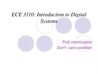
ECE 2110: Introduction to Digital Systems
150 likes | 290 Vues
This course provides an overview of logic function minimization in digital systems, focusing on techniques such as Karnaugh maps. Students will learn how to simplify logic functions to reduce the number and size of gates, starting from truth tables or minterm lists. The course covers algebraic simplification, the application of theorems (T9, T10), and the construction of Karnaugh maps for up to five variables. Emphasis is placed on reducing circuit costs by minimizing the number of gates and their inputs, while assuming access to both true and complemented versions of input variables.

ECE 2110: Introduction to Digital Systems
E N D
Presentation Transcript
ECE 2110: Introduction to Digital Systems Minimization Karnaugh Maps
Minimization • Logic Function minimization : Simplifying the logic function to reduce the number and size of gates. • Minimization methods:1- Using theorems T9,T9’, T10,T10’ 2- Karnaugh map
Algebraic simplification • Starting from a truth table, or a minterm (maxterm) list • Reduce the cost of a 2-level circuit: • Minimize # of first-level gates • Minimize # of inputs of gates • Do not consider the cost of input inverters: assuming that both true and complemented versions of all input variables are available.
Algebraic simplification • T10, X.Y+X.Y’=X T10’: (X+Y).(X+Y’)=X • Generalization of the theorems: • (Given product term).Y+(Given product term).Y’= Given product term • (Given product term+Y).(Given product term+Y’)= Given product term • Reduce number of gates and gate inputs
Algebraic simplification • Theorem T10, • Reduce number of gates and gate inputs
Karnaugh Maps • Karnaugh Map : a representation of the truth table by a matrix of squares (cells) , where each square corresponds to a minterm ( or a maxterm) of the logic function. • For n-variable function, we need 2^n rows truth table and 2^n squares (cells). • The square number is equivalent to the row number in the truth table • To represent a logic function, the truth table values are copied into their corresponding cells . • The arrangements of the squares help to identify the input variable redundancy ( X.Y.Z+X.Y.Z’=X.Y )
Two-variable Karnaugh map • Example : F = X.Y’+X.Y • Simplification : F = X(Y+Y’) = X.1 = X • Also proven by T(10) X X ROW X Y F 0 1 Y 0 0 0 0 0 2 0 0 1 1 0 1 0 1 3 1 Y 2 1 0 1 0 1 3 1 1 1
Two-variable Karnaugh map • Example : F = X’.Y’+X’.Y • Simplification : F = X’(Y+Y’) = X’.1 = X’ • Exercise : Can we simplify FX,Y= SX,Y (1,2) ? X X ROW X Y F 0 1 Y 0 0 0 1 0 2 0 1 0 1 0 1 1 1 3 1 Y 2 1 0 0 1 0 3 1 1 0
3-variable Karnaugh map • Can we simplify FX,Y,Z = Sx,y,z (1,3,5,7) ?
Example : F=X’.Y’.Z’+X’.Y’.Z+X.Y’.Z’+X.Y’.Z Row X Y Z F 0 0 0 0 1 1 0 0 1 1 2 0 1 0 0 3 0 1 1 0 4 1 0 0 1 5 1 0 1 1 6 1 1 0 0 7 1 1 1 0 F = X’.Y’.(Z’+Z)+X.Y’.(Z’+Z)=X’.Y’+X.Y’=(X’+X).Y’ = Y’ Three-variable Karnaugh map X XY 00 01 11 10 Z 0 2 6 4 0 1 0 0 1 1 3 7 5 1 Z 1 0 0 1 Y
Five-variable Karnaugh map • Five variable K-map is formed using two connected 4-variable maps: V VWX W W 000 001 011 010 100 101 111 110 YZ 0 4 12 8 16 20 28 24 00 1 5 13 9 17 21 29 25 01 Z 3 7 15 11 19 23 31 27 11 Y 2 6 14 10 18 22 30 26 10 X X
Next: • Simplifying SOP