KMOS operations and performance
650 likes | 811 Vues
This presentation outlines the operational principles and performance requirements for the KMOS instrument, discussed during the ESO IST meeting on May 10, 2006. Key topics include observation preparation, configuration of instrument arms, calibration procedures, and post-processing steps necessary for optimal performance. The design aims to meet essential and desirable requirements while ensuring compliance with ESO standards. Emphasis is placed on the efficiency of sky subtraction options and the management of observations for various types of celestial targets.

KMOS operations and performance
E N D
Presentation Transcript
KMOS operations and performance Presentation to the KMOS ESO IST, 10th May 2006
KMOS operations • Observation preparation • Configuring the arms • Sky subtraction options • During the observations • Source acquisition • Observation of calibration stars • After the observations • Daytime calibration • Post processing steps KMOS IST meeting, ESO, 10tth May 2006
Setting the requirements • Performance requirements are specified • Essential • the design must be meet these requirements and is verified against them • Optimal • Achieving these represents a significant scientific gain and our goal is for the design to meet these • Desirable • to be met if can be met with minimal impact on the design/cost/schedule • Not all requirements have multiple levels KMOS IST meeting, ESO, 10tth May 2006
General operations principles • Building on experience with NIR IFU instruments within the consortium • SINFONI, GNIRS, UIST • Building on ESO experience with the aim of producing an operational model compliant with ESO standards and practice KMOS IST meeting, ESO, 10tth May 2006
Preparation of the observations Performance information Configuration of the arms Sky subtraction mode
Req 3.5.1: Throughput KMOS IST meeting, ESO, 10tth May 2006
Detector moduleHawaii RG2 arrays from Rockwell (2048x2048 pixels), results from Gert Finger KMOS IST meeting, ESO, 10tth May 2006
Req 3.5.2: Instrument thermal background • Design follows best practice of light tight croystat, use of baffling. KMOS IST meeting, ESO, 10tth May 2006
Sensitivity model KMOS IST meeting, ESO, 10tth May 2006
Sensitivity model KMOS IST meeting, ESO, 10tth May 2006
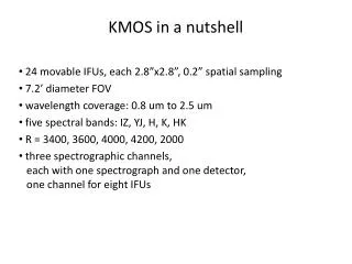
Arm configuration • 24 arms (req 3.5.12) are configured within 7.2’ field (req 3.5.9) using KARMA • Fields of view • 2.8arcsec x 2.8arcsec IFU fields (Req 3.5.10) • 0.2arcsec in both spatial directions (Req 3.5.9) • Anamorphic magnification in the IFUs KMOS IST meeting, ESO, 10tth May 2006
Arm configuration • Arms are configured using KARMA • Automatic configuration based on rules and optional manual configuration • Input catalogue: • source positions with priority • Band 1 – highest priority, must be observed • Band 2 – reduced priority, should be selected over a Band 3 object • Band 3 – lowest priority, could be deselected with little loss to the programme. KMOS IST meeting, ESO, 10tth May 2006
Arm configuration • Input catalogue: • Positions of objects with priority • Positions of reference stars for acquisition • Position of guide star • Optional positions for sky with priority • Optional positions of bright stars to avoid • Input image: • Required • Not used to derive object positions • Used to identify sky positions KMOS IST meeting, ESO, 10tth May 2006
Arm configuration • Set of rules • No collisions between arms • Never violated • Closest approach includes margin for atmospheric refraction • No vignetting • May be violated, flag set in the file header • Will avoid bright objects (K<12) hitting an arm • May be overridden in ‘manual’ mode KMOS IST meeting, ESO, 10tth May 2006
Requirements on arm positioning • Req 3.5.15: Close packing of target fields • ≥ 10 fields within 1arcminute • Req 3.5.16: Simultaneous observations of close packed fields • ≥ 3 fields within more than one 1arcminute field • ≥ 10 fields within more than one 1arcminute field, within a restricted patrol field KMOS IST meeting, ESO, 10tth May 2006
Access to clusters KMOS IST meeting, ESO, 10tth May 2006
Requirements on arm positioning • Req 3.5.17: Closest approach of target fields • 12 pairs of two target fields within 6arcsec edge-to-edge • Best seen in the mapping mode KMOS IST meeting, ESO, 10tth May 2006
Fixed arm configurations • For observations of the calibration source • For observations of calibration stars • For mapping mode KMOS IST meeting, ESO, 10tth May 2006
Mapping mode (req 3.5.16) • Arms set to a regular grid on the sky • Single configuration, fixed by arm mech. design • Telescope offsets to execute a jitter pattern • 0.75 square arcmin in 16 moves • TBD whether available in service mode KMOS IST meeting, ESO, 10tth May 2006
Sky subtraction modes • Four modes of sky subtraction provided for in the PDR design • Experience from other instruments being brought to bear • Flexibility to explore the most efficient options during commissioning • Sky subtraction mode impacts the flat-field requirements KMOS IST meeting, ESO, 10tth May 2006
Sky Subtraction: Offsetting Objects • Single set of objects is offset between arms • 50% of time spent on source; 50% on sky • Object and sky observed along same optical path/same pixels • Flat-field accuracy requirements ~1% KMOS IST meeting, ESO, 10tth May 2006
Object is offset between arms Observing objects in the ‘offset’ beam improves efficiency, but may be hard to achieve in real sources? Object and sky observed along same optical path/same pixels Flat-field accuracy requirements ~1% Sky subtraction: Offset frames KMOS IST meeting, ESO, 10tth May 2006
Sky Subtraction: Source fields • Sky signal obtained from the periphery of the IFU fields • Highly efficient • Flat-field accuracy requirements ~0.1% • Achieved through a combination of flat-field observation and scaling OH lines KMOS IST meeting, ESO, 10tth May 2006
Arms not assigned to objects are used to observe sky Requirements on flat-fielding are that sky signal must be calibrated to 0.1% Achieved through combination of flat-field and post-processing Subtraction: Sky arms KMOS IST meeting, ESO, 10tth May 2006
Other configurable parameters • Exposure time • Time to reach the background limit TBD, but around 600s • Non-destructive read-out will be standard • Spectrometer • User selected wavelength band • The same grating and appropriate filter selected for all three spectrographs • Achromatic spectrograph, so no focus KMOS IST meeting, ESO, 10tth May 2006
Spectroscopic modesReq 3.5.5: Total wavelength coverage • At PDR, four options: IZ, J, H, K • Extension to 0.8um is optimal requirement • i.e. coatings, IQ etc are acceptable • Requires additional IZ grating and filter, discussed later….. • Additional, broader l coverage (JH/HK) gratings with lower R TBD during FDR phase (req 3.5.20) KMOS IST meeting, ESO, 10tth May 2006
Spectroscopic modes3.5.21: Wavelength multiplex advantage • ‘Optimal’ requirement and initial KMOS concept to configure 3 spectrometers with different gratings, different DITs • Opted for single detector controller, therefore different DITs not possible • Multi-grating option not implemented KMOS IST meeting, ESO, 10tth May 2006
3.5.19: Spectral resolving power Spectral resolving power secondary to wavelength coverage IZ:0.8-1.05um; J:1.05-1.37um; H:1.45-1.85um; K:1.95-2.50um KMOS IST meeting, ESO, 10tth May 2006
During the observations Source acquisiton Calibration stars
Observational efficiency • Req 3.5.8: Desirable requirement for >85% efficiency in one hour gives 9minute budget • Instrument configured during 6min telescope preset • Predicted 1min for observations of reference objects during acquisition. Budget ~3min. • Additional ~1min required if reconfiguring arms for different science targets KMOS IST meeting, ESO, 10tth May 2006
On loading the arm configuration • Arm positions recalculated for the airmass at the start of observations • In the case of a failed arm, the requested rotation of the field is altered until the allocation of arms to high priority targets is optimised KMOS IST meeting, ESO, 10tth May 2006
Arm failure and related responses • Impact of an arm failure • 1/24 loss of efficiency measured simply by non-availability of an arm • Thoughtful arm design has ensured that one arm does not block others • Modelling with KARMA suggests ~1 objects no longer accessible in ‘standard’ clusters. • Can be improved by reselecting rotation KMOS IST meeting, ESO, 10tth May 2006
Acquisition with KMOS • Acquisition to ±(0.5,0.5) spatial elements • Repeat positioning to <±0.2arcsecs KMOS IST meeting, ESO, 10tth May 2006
Acquisition Steps • Configure KMOS during telescope preset • For three bright reference sources or for science field • Acquire guide star • Targets should be acquired now • Observe, determine centroids • Apply systematic offset as required • Ignore small (<~0.2arcsec) random offsets • If sources are not seen, start a different OB KMOS IST meeting, ESO, 10tth May 2006
Acquisition with KMOS • In visitor mode only (req 3.5.11) • Small (< 1 field) adjustments of arms subject to rules KMOS IST meeting, ESO, 10tth May 2006
What changes during the observations? • Nothing • No movement of the arms • Not for sky positions • Not for atmospheric refraction • No flexure compensation • Not for spectroscopic shifts • Not for image movements/flexure • NB: change from Phase A concept KMOS IST meeting, ESO, 10tth May 2006
More on Spectral flexure • Sources • Flexure of the pseudo-slit relative to the spectrograph • Flexure of the detector+mount relative to slit • Flexure of the grating • Design has flexure within acceptable limits (req 3.5.23: <0.2pixels) • If as-built flexure is unacceptable, calibrate with OH lines • Technique developed on SINFONI KMOS IST meeting, ESO, 10tth May 2006
More on image movement • Sources • Bulk motion of the instrument relative to the Nasmyth flange • Relative movements of the arms • Relative motions of the arms cannot be compensated • Arm design meets the requirements on flexure • NB not a peculiarity of the arms KMOS IST meeting, ESO, 10tth May 2006
More on image movement • Bulk motion of the cryostat • Produces shifts in the images • Blind co-addition of images will result in combined PSF of 0.49arcsec over 1 hour in 0.4arcsec seeing • Compensated by post-processing of images • BUT NB this does not include detector cross-talk and assumes ZD>10degrees • Produces a shift of the spectral lines in conditions of the best seeing • 5% increase in line width • ±0.23pixels movement of the centroid • NB this does not affect subtraction of sky lines KMOS IST meeting, ESO, 10tth May 2006
Observation of calibration stars • Fixed arm configuration • Telluric standard from one arm • Option to repeat once per spectrograph • Three arms deployed into the field • offset telescope • Flux calibration • Via the telluric standard or a flux standard • Relative throughput of arms scaled from sky background KMOS IST meeting, ESO, 10tth May 2006
After the observations Daytime calibration Post processing steps
Calibration system KMOS IST meeting, ESO, 10tth May 2006
Dedicated calibration unit containing Two tungsten lamps for flat fielding (one plus spare) One argon lamp for wavelength calibration Calibration lamps KMOS IST meeting, ESO, 10tth May 2006
Flat-fielding • Continuum source in the calunit • Provide spatially+spectrally smooth field • Modelled spatial uniformity: • Few-% (possibly better…..) • Sphere to be built and tested during FDR phase • To remove vignetting function, flat-field on sky with arms in deployed position • Twilight flats provided for, but not routine KMOS IST meeting, ESO, 10tth May 2006
Wavelength calibration • Argon arc lamp expected to provide wavelength calibration to <0.1pixel (±2.5kms-1) • req 3.5.24 on wavelength scale accuracy met • Requirement (3.5.22) on velocity precision of ±10kms-1 met • Including allowance for predicted movement of the centroid in best seeing KMOS IST meeting, ESO, 10tth May 2006
Spatial calibration established in the lab Spectral curvature Offsets of the IFU slitlets Image reconstruction: in the lab KMOS IST meeting, ESO, 10tth May 2006