
Logic Gate Characteristics & Families
E N D
Presentation Transcript
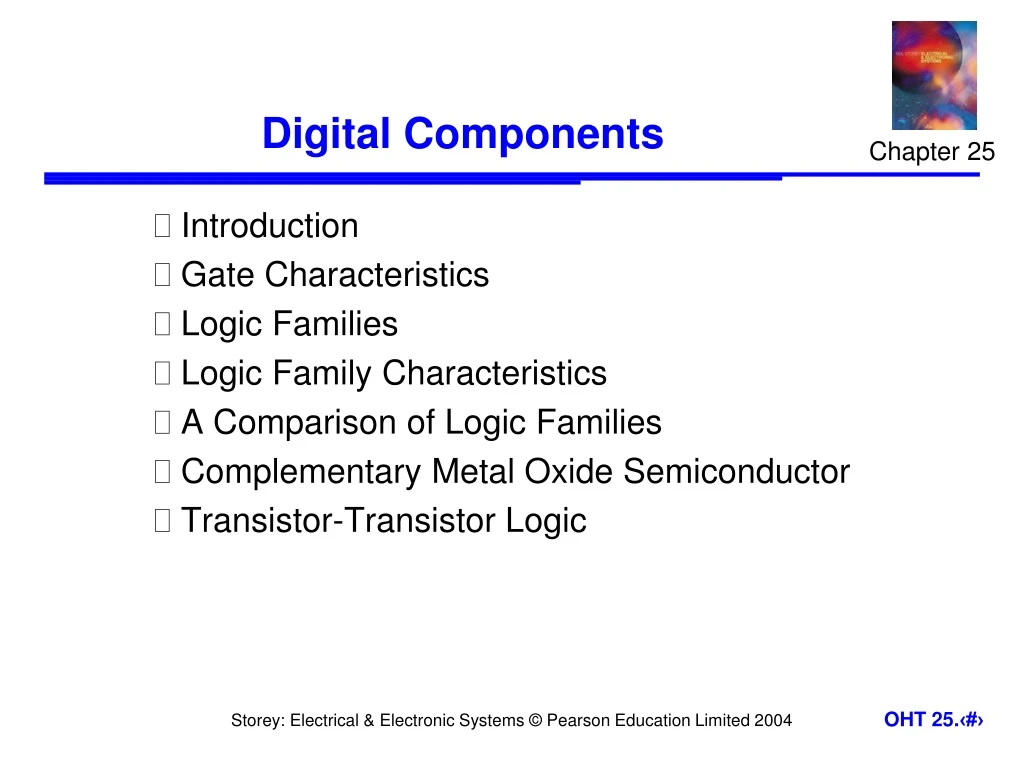
Chapter 25 Digital Components • Introduction • Gate Characteristics • Logic Families • Logic Family Characteristics • A Comparison of Logic Families • Complementary Metal Oxide Semiconductor • Transistor-Transistor Logic
25.1 Introduction • Earlier we looked at a range of digital applications based on logic gates – at that time we treated the gates as ‘black boxes’ • We will now consider the construction of such gates, and their characteristics • In this lecture we will concentrate on small- and medium-scale integration circuits containing just a handful of gates • typical gates are shown on the next slide
Logic levels • the voltage ranges representing ‘0’ and ‘1’ represent the logic levels of the circuit • often logic 0 is represented by a voltage close to 0 V but the allowable voltage range varies considerably • the voltage used to represent logic 1 also varies greatly. In some circuits it might be 2-4 V, while in others it might be 12-15 V • in order for one gate to work with another the logic levels must be compatible
Noise immunity • noise is present in all real systems • this adds random fluctuations to voltages representing logic levels • to cope with noise, the voltage ranges defining the logic levels are more tightly constrained at the output of a gate than at the input • thus small amounts of noise will not affect the circuit • the maximum noise voltage that can be tolerated by a circuit is termed its noise immunity,VNI
Rise and fall times • because the waveforms are not perfectly square we need a way of measuring switching times • we measure the rise time, tr and fall time, tf as shown below
Timing considerations • all gates have a certain propagation delay time, tPD • this is the average of the two switching times
25.3 Logic Families • We have seen that different devices use different voltages ranges for their logic levels • They also differ in other characteristics • In order to assure correct operation when gates are interconnected they are normally produced in families • The most widely used families are: • complementary metal oxide semiconductor (CMOS) • transistor-transistor logic (TTL) • emitter-coupled logic (ECL)
25.4 Logic Family Characteristics • Complementary metal oxide semiconductor (CMOS) • most widely used family for large-scale devices • Low power consumption • usually operates from a single supply of 5 – 15 V • excellent noise immunity of about 30% of supply voltage • Fan out: can be connected to a large number of gates (about 50) • many forms – some with tPD down to 1 ns • power consumption depends on speed (perhaps 1 mW)
Transistor-transistor logic (TTL) • based on bipolar transistors • one of the most widely used families for small- and medium-scale devices – rarely used for VLSI • typically operated from 5V supply • typical noise immunity about 1 – 1.6 V • many forms, some optimised for speed, power, etc. • high speed
Emitter-coupled logic (ECL) • based on bipolar transistors, but removes problems of storage time by preventing the transistors from saturating • very fast operation - propagation delays of 1ns or less • high power consumption, perhaps 60 mW/gate • low noise immunity of about 0.2-0.25 V • used in some high speed specialist applications, but now largely replaced by high speed CMOS
25.5 A Comparison of Logic Families