Download
1 / 24
380 likes | 722 Vues
CHAPTER 9. FARADAY’S LAW AND DISPLACEMENT CURRENT. 9.1 FARADAY’S LAW 9.1.1 TIME VARYING FIELD – STATIONARY CIRCUIT 9.1.2 MOVING CIRCUIT – STATIC FIELD 9.1.3 TIME VARYING FIELD - MOVING CIRCUIT 9.2 DISPLACEMENT CURRENT 9.3 LOSSY DIELECTRICS 9.4 BOUNDARY CONDITIONS.

E N D
CHAPTER 9 FARADAY’S LAW AND DISPLACEMENT CURRENT 9.1 FARADAY’S LAW 9.1.1 TIME VARYING FIELD – STATIONARY CIRCUIT 9.1.2 MOVING CIRCUIT – STATIC FIELD 9.1.3 TIME VARYING FIELD - MOVING CIRCUIT 9.2 DISPLACEMENT CURRENT 9.3 LOSSY DIELECTRICS 9.4 BOUNDARY CONDITIONS
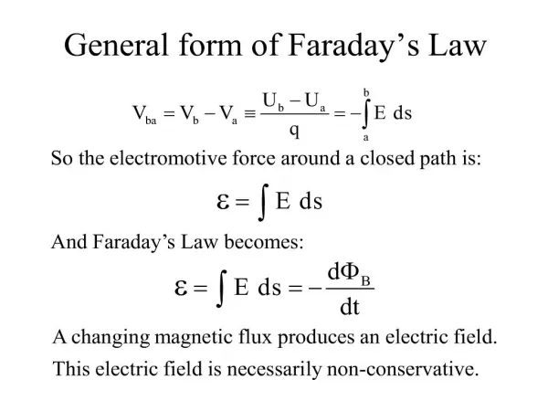
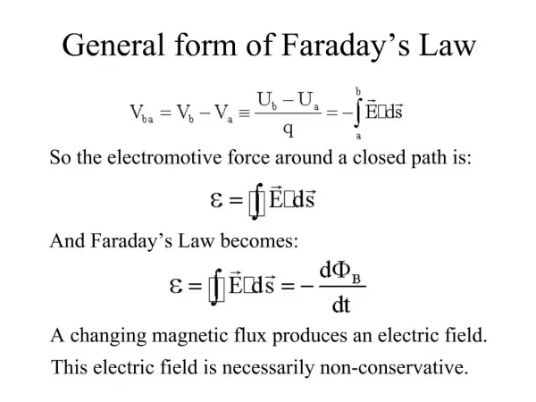
Two topics will be discussed : • Faraday’s Law – about the existence of electromotive force (emf) in the magnetic field • Displacement current – that exists due to time varying field That will cause the modification of Maxwell’s equations (in point form - static case) studied previously and hence becomes a concept basic to the understanding of all fields in electrical engineering. 9.0 FARADAY’S LAW AND DISPLACEMENT CURRENT
Loop Flux linkage - + Battery Galvanometer 9.1 FARADAY’S LAW Michael Faraday – proved that if the current can produce magnetic field, the reverse also will be true. Proven only after 10 years in 1831. The magnetic field can produce current in a loop, only if the magnetic flux linkage the surface of the loop is time varying. Faraday’s Experiment :
Loop Flux linkage - + Battery Galvanometer • Current produced magnetic field and the magnetic flux is given by : (1) • No movement in galvanometer means that the flux is constant. • Once the battery is put off – there is a movement in the galvanometer needle. • The same thing will happen once the battery is put on - but this time the movement of the needle is in the opposite direction. Conclusions : The current was induced in the loop • when the flux varies • once the battery is connected • - if the loop is moving or rotating
Loop Flux linkage - + Battery Galvanometer Induced current will induced electromotive voltage or induced emf Vemf given by : (2) where N = number of turns Equation (2) is called Faraday’s Law Lenz’s Law summarizes the –ve sign is that : The induced voltage established opposes the the flux produced by the loop.
In general, Faraday’s law manifests that the Vemf can be established in these 3 conditions : • Time varying field – stationary circuit (Transformer emf) • Moving circuit – static field (Motional emf) • Time varying field - Moving circuit (both transformer emf and motional emf exist)
I 1 R 2 Diagram shows a circle loop with the surface area S placed in the magnetic field increases induced 9.1.1 TIME VARYING FIELD – STATIONARY CIRCUIT (TRANSFORMER EMF) (3) Vemf = the potential difference at terminal 1 and 2. From electric field : (4) If N = 1 : (5)
Using Stoke’s theorem : (6) Hence Maxwell’s equation becomes : (7)
Moving bar Diagram shows a bar moving with a velocity in a static field . Hence : 9.1.2 MOVING CIRCUIT – STATIC FIELD (MOTIONAL EMF) Force : Fleming’s Right hand rule Thumb – Motion 1stfinger – Field Second finger - Current
9.1.3 TIME VARYING FIELD - MOVING CIRCUIT Both transformer emf and motional emf exist
A bar position at y = 8 cm and • A bar moving with a velocity and • A bar moving with a velocity and P 0 y 6 cm Q x Ex. 9.1 : A coducting bar moving on the rail is shown in the diagram. Find an induced voltage on the bar if :
P y 0 6 cm Q x z y x According to Lenz’s law when increases point P will be at the higher potential with respect to point Q. (B induced will oppose the increasing ) Remember : the direction of is opposed the current induced in the loop. Solution : (i) Transformer case : (ii) Motional case :
P y 0 6 cm Q x z y x (iii) Both transformer and motional case :
; and 9.2 DISPLACEMENT CURRENT From continuity of current equation : and Hence :
R Jc + C +Q Jd - -Q = Conduction current density Dielectric where : = Displacement current density Hence : Therefore from Faraday’s law and the concept of displacement current we can conclude that both the magnetic and electric fields are interrelated.
Differential Form Integral Form Label Maxwell’s Equations Faraday’s Law Ampere’s Circuital Law Gauss’S Law for Electric Field Gauss’s Law for Magnetic Field An integral form of Maxwell’s equation can be found either by using Divergence Theorem or Stoke Theorem.All electromagnetic (EM) waves must conform or obey all the four Maxwell’s equations.
Ex.9.2: A parallel plate capacitor having a plate area of 5 cm2 and where the plates are separated by a distance of 3 mm is connected to a supply voltage, 50 sin 103 t Volt. Calculate the displacement current if the dielectric permittivity between the plate is . Solution :
Ex.9.3: Given a magnetic medium with characteristics has . Find and . This example is to show the use of Maxwell’s equation and the inter relation of electric field and magnetic field. Solution : ;
Compare : Hence :
For a perfect dielectric : Hence Maxwell’s equation : 9.3 LOSSY DIELECTRICS Main function of dielectric material is to be used as an insulator. Compare (1) and (2) : (1) For lossy dielectric : where : (2) = loss tangent Loss tangent is the ratio of the magnitude of the conduction current density to the magnitude of the displacement current density
+ + + + + + C R Leakage current -ve From page 110 & 111 - - - - - and Hence loss tangent : A lossless capacitor has a loss tangent of zero. For lossy capacitor, an equivalent circuit can be replaced by its equivalent resistance in parallel with a perfect capacitor as shown in the diagram :
Ex.9.4: Find the average power loss per unit volume for a capacitor having the following properties; dielectric constant 2.5 loss tangent 0.0005 for an applied electric field intensity of 1 kV/m at frequency 500 MHz. Solution :
Normal components : If medium 2 is perfect conductor : Tangential components for and : Hence : 9.4 BOUNDARY CONDITIONS Boundary conditions for time varying field are the sameas boundary conditions in electrostatics and magnetostatics fields.