Thermocouples and Their Calibration
470 likes | 1.87k Vues
Thermocouples and Their Calibration. Prepared By: Adeel Tariq 2007-chem-04. What is Thermocouple ?.

Thermocouples and Their Calibration
E N D
Presentation Transcript
Thermocouples and Their Calibration Prepared By: Adeel Tariq 2007-chem-04
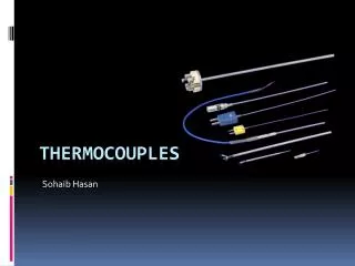
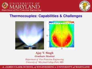
What is Thermocouple? • A thermocouple or thermocouple thermometer is a junction between two different metals that produces a voltage related to a temperature difference. Thermocouples are a widely used type of temperature sensor for measurement and control and can also be used to convert heat into electric power.
Working principle The working principle of thermocouples depends on the see beck effect. See beck effect: The Seebeck effect states when two dissimilar metal wire are connected with each other in a loop to form two junctions, maintained at two different temperatures, a voltage potential or electromotive force (E=emf) will be generated and the current will flow through the loop circuit.
Thermocouple types • The four most common calibrations are J, K, T and E. Each calibration has a different temperature range and environment, although the maximum temperature varies with the diameter of the wire used in the thermocouple. TCs are identified by a single letter type and grouped according to their temperature range • Base Metals – up to 1000 °C • Type J, Type E, Type T, Type K • Noble Metals – up to 2000 °C • Type R, Type S, Type B • Refractory Metals – up to 2600 °C • Type C, Type D, Type G
Selection of Thermocouple • The following criteria are used in selecting a thermocouple: • Temperature range (Industry generally prefers K and N types because of their suitability to high temperatures). • Chemical resistance of the thermocouple or sheath material (including corrosion resistance). • Abrasion and vibration resistance. • Installation requirements (may need to be compatible with existing equipment; existing holes may determine probe diameter) i.e. the ease of use is important. • Sensitivity of thermocouple (the T type is usually favored by industries on this basis). • Cost.
Thermocouple calibration • A thermocouple is calibrated by comparing its response with a standard thermometer at the same temperature. The standard thermometer may be another thermocouple, a platinum resistance thermometer or a liquid in glass thermometer.
The thermocouples are calibrated by one or more of three general methods, depending on • the type of thermocouple, • the temperature range, • the accuracy required
Methods to calibrate thermocouples • In the first method, thermocouples are calibrated by comparison with a reference thermocouple. • In the second method, thermocouples are calibrated against a standard platinum resistance thermometer. . • In the third method, thermocouples are calibrated at four defining temperatures of the ITS-90: the freezing points of zinc, aluminum, silver, and gold
Calibration procedure Controlled temperature source: The temperature source used in the process of calibrating should be stable enough to provide a constant temperature for a short length of time at any temperature at which the temperature bath or other source is to be used.
Reference junction temperature • A controlled temperature must be provided in which the reference junction is maintained at a constant chosen temperature. The most commonly used reference temperature is 32 degrees F., but other temperatures may be used if desired.
Measuring instruments: The choice of a specific instrument for measuring the thermocouple output will depend on the accuracy required of the calibration being performed. Reference thermometers: The reference thermometer to be used for the comparison calibration of a thermocouple will depend upon • the temperature range covered, • the accuracy desired, • the capabilities, • the preference of the calibration laboratory.
Types of reference thermometer • Platinum resistance thermometers • Water in glass thermometer
Depth of immersion • Depth of immersion is the most important consideration if accurate calibration results are to be obtained. The depth of immersion must be sufficient to eliminate the effects of heat transfer away from the junction.
Measurement • Set your controlled temperature source to the specified temperature and allow it to adequately stabilize. • Immerse the test assembly into the test temperature medium and provide sufficient time for the test assembly to stabilize. • Once the test assembly is stable the EMF generated between the test specimen and the reference standard can be recorded
Continued • Once the reading is taken, raise the test temperature to the next higher temperature, first removing the test assembly from the temperature source, or advance the test assembly to the next temperature source. • Allow the temperature source and the test assembly to stabilize as before, and take a second set of readings at the new temperature. • In all cases take the reading in sequence from the lowest to the highest temperature.
Procedure • Check the level of water in the bath. Connect the apparatus to the Power supply. • Turn on the water bath by switching the main switch (1) as shown in the figure. • Keep the set-in switch (8) depressed and set the temperature to desired level (30 deg C to start) by turning the knob(6) and observing the display(7). Release the switch(8) after setting the temperature. In normal mode, the temperature shown on the digital display is the actual temperature of the bath (TB) against which the thermocouple sensor is to be calibrated. • Connect the ends of the thermocouple to the digital multimeter (MM) and set the multimeter to read in millivolts DC
Dip one junction of the thermocouple in the thermo-bath liquid and wait for few minutes for it to reach the steady state (i.e. the reading on the MM steadies down except the last digit). Be careful to hold (tape) the sensor wire away from the circulator's propeller! Note down the digital MM reading in millivolts (EMM) and repeat the steps 3 through 6 in steps of 5 degrees from 30 to 60 degrees Celsius. • To calibrate the thermocouple, we have to take the room temperature into consideration to get the absolute value of temperature measured. Find the equivalent millivolt value for the room temperature from the corresponding Thermocouple table (ERM). Then, add that millivolt value, corresponding to the room temperature, to every multimeter reading (EMM). Tabulate the values
Plot the measured bath temperatures values (TB) on y-axis against the corresponding thermocouple emf (millivolt) values (E) on x-axis. Find the slope, intercept and the correlation coefficient of the curve-fitted line by any method. If the correlation coefficient is not very close to one, curve fit with higher order polynomial. Calculate the 95% uncertainty in temperature measurement of the calibrated thermocouple sensor if the obtained curve-fit correlation is used.