Hub
Hub. The Only Co- S imulation Tool of Its Kind on the Market. Hub. Perform Co- S imulation of Designs E asily. Ensure Parts Work Together Before Silicon. Introduction. Why to do Co-Simulation? Two verification environments use different simulators ? ?. VCS-based

Hub
E N D
Presentation Transcript
Hub The Only Co-Simulation Tool of Its Kind on the Market
Hub Perform Co-Simulation of Designs Easily Ensure Parts Work Together Before Silicon
Introduction • Why to do Co-Simulation? • Two verification environments use different simulators • ? ? VCS-based RTL/Gate HDL Design Testbench Monitors Checkers Drivers BFM’s … Modelsim-based RTL/Gate HDL Design Testbench Monitors Checkers Drivers BFM’s … VCS-based RTL/Gate HDL Design Testbench Monitors Checkers Drivers BFM’s … VCSMX-based RTL/Gate HDL Design Testbench Monitors Checkers Drivers BFM’s …
Introduction • Why to do Co-Simulation? • Two verification environments are too complex to be put under one testbench. • ? Very Complex Env RTL/Gate HDL Design Testbench Monitors Checkers Drivers BFM’s … Very Complex Env RTL/Gate HDL Design Testbench Monitors Checkers Drivers BFM’s …
Introduction • Why to do Co-Simulation? • Two environments together exceed computer memory size • Could not be simulated on 4G machine. • Solution: • Use 8G machine or • Co-Simulate on two 4G machines 2.5G Model RTL/Gate HDL Design Testbench Monitors Checkers Drivers BFM’s … 2.5G Model RTL/Gate HDL Design Testbench Monitors Checkers Drivers BFM’s …
Introduction • Why to do Co-Simulation? • One design is Verilog, the other is VHDL • ? • Not all simulators perform mixed Verilog-VHDL simulation. • Solution: • Use Co-Simulation tool. Verilog RTL/Gate HDL Design Testbench Monitors Checkers Drivers BFM’s … VHDL RTL/Gate HDL Design Testbench Monitors Checkers Drivers BFM’s …
Introduction • Why to do Co-Simulation? • Two designs are physically in distant locations. • ? • Solution: • Co-Simulate over the Internet. • Do not have to share IP’s. • Only interface information is shared. In Tokyo, Japan RTL/Gate HDL Design Testbench Monitors Checkers Drivers BFM’s … In Sunnyvale, CA RTL/Gate HDL Design Testbench Monitors Checkers Drivers BFM’s …
Introduction • Hub allows the simulated models to communicate • over the network or • on a single computer
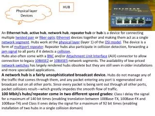
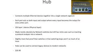
Hub Overview • Hub has three main components: • hub executable • Runs on the network. • Communicates with the simulators. • hub_ifc shared library • Used by the simulators to communicate with hub. • Verilog hook-up module (optional, but recommended) • Instantiated by both simulated models. • Has interface signals. • Has PLI call to communicate with hub.
Hub Overview hub • hub • Communicates with the simulators. • hub_ifc shared library • Used by the simulators to communicate with hub. comp1 hookup hub_ifc comp2 hub_ifc hookup
Hub Overview hub comp1 hookup hub_ifc comp2 hub_ifc hookup • Verilog hook-up module module hookup(clk, reset, Q, QQ); input clk, reset; input [3:0] Q; output [3: 0] QQ; reg [3:0] QQ; always @(posedgeclk) begin $hub_event_comp1; end endmodule module hookup(clk, reset, Q, QQ); input clk, reset; input [3:0] Q; output [3: 0] QQ; reg [3:0] QQ; always @(posedgeclk) begin $hub_event_comp2; end endmodule Comp1 Comp2
Hub Overview • Verilog Interface Signals • Output Signals • Can be from any place in the Verilog design hierarchy. • Must be an input to a module. • It is recommended to bring all the signals to be transmitted to the hook-up module. • Input Signals • Must be declared as reg somewhere. • It is recommended to declare them in the hook-up module and make them outputs of the hook-up module.
Hub Overview • Hook-up modules in both simulated models Network top top Comp1 hookup Comp2 hookup comp1_out1 comp2_in1 8 8 reg comp1_out2 comp2_in2 reg comp1_in1 comp2_out1 4 4 reg
Hub Overview • Interface files (comp1.ifc and comp2.ifc) • Hub and hub interfaces of the simulated models need information about the interface signals. • The user must put comp1.ifc and comp2.ifc in the run directory. • The tool does complete check of the ifc files before run. • Checks input/output • Checks signal path • Checks signal width • Any errors are reported in parse_ifc_err.out in the run directory comp1.ifc comp2.ifc output top.hookup.comp1_out1 8 output top.hookup.comp1_out2 1 input top.hookup.comp1_in1 4 input top.hookup.comp2_in1 8 input top.hookup.comp2_in2 1 output top.hookup.comp2_out1 4
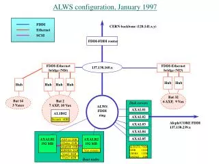
Hub Overview • Host file - hub.host • The simulated models have to be aware of the IP address of the Hub computer. • Assign two available ports for Hub to communicate with the simulated models. • The user must put the host file in the run directory. hub.host ip 192.168.0.6 comp1_port 9733 comp2_port 9734
Hub Overview • Hub configuration file – hub.cfg • Specify hub timeout before it is connected to the simulated models in sec (for example, 60) • Specify hub timeout after it is connected to the simulated models in sec (for example, 10) • The user must put hub.cfg in the run directory. hub.cfg timeout_before_connect 60 timeout_after_connect 10
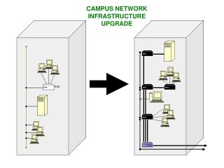
Tool Demonstration Setup • A Linux LAN consists of two machines • Two Linux computers are connected through a router. • The machines are named host1 and host2. • The machines have IP address 192.168.0.6 and 192.168.0.7 • SLURM (Simple Linux Utility for Resource Management) • We use SLURM to submit Hub and both simulation models to any machine in the LAN. • The two communicating Verilog designs are called Counter and Follower • Counter is a four bit counter with an active low reset. • Four bit Counter output and the reset are transmitted to Follower. • Follower implements another counter that increments only when the Counter output reaches 4’bf. Follower resets when reset is asserted. • The output of the Follower is sent back to the counter model.
Tool Demonstration Setup • The Verilog simulator used on this project is Icarus Verilog. • Free IEEE compliant Verilog simulator developed by Stephen Williams • Shell scripts to automatically compile both Hub and Verilog designs are created.