Download
1 / 5
50 likes | 128 Vues
Study of applied weight variations for matching model to measured x-ray power through filters at different energies, with two solutions found for optimal power distribution.

E N D
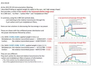
2012-06-04 At the 2012-05-30 Instrumentation Meeting, I described finding an applied weight (to apply to the sync. rad. high energy shape) that provides a match of the model to the measured relative image areas for 2.085 GeV , “no filter”, “carbon filter” and “molybdenum filter” In summary, using the 2.085 GeV pinhole data, and matching to the relative transmission through the 4 μm carbon and 2 μm molybdenum filters, there are two solutions to decreasing the low energy x-ray power. These are shown with the unfiltered power distribution and the power distribution filtered by carbon. ( 2a ) With { 0.063, 0.620 } applied weight in bins 1,2, Molybdenum: the relative transmitted power = 1549/31547= 0.0491 Carbon: the relative transmitted power = 16367/31547= 0.519 . ( 3a ) With { 0.047, 0.094, 0.375 } applied weight in bins 1,2, 3, Molybdenum: the relative transmitted power = 627/12748= 0.0490 Carbon: the relative transmitted power = 6647/12748= 0.522 . They are very different. They both satisfy the observed relative transmissions for the carbon and molybdenum filters (2 pieces of information). ( The 3-bin solution has the added constraint that the ratio of the applied transmission of bin 2 to that of bin 1 is 2:1 . )
2012-06-04 Include the 1.800 GeV and 2.300 GeV pinhole data. The normalized (total power in image)/(beam current) i.e. (image area)/[(beam current) x (electronic gain)] for 2.085 and 1.800 and 2.3 GeV data is shown below. We did not take 2.300 GeV without filter; that was a mistake. (Red is the new information.) DATA no filter carbon filter molybdenum filter 1.800 GeV 0.304 0.079 2.085 GeV 1 0.520 0.050 2.300 GeV --- 1.611 0.251 ( 2a ) With { 0.063, 0.620 } applied weight in bins 1,2, no filter carbon filter molybdenum filter 1.800 GeV 0.306 0.115 2.085 GeV 1 0.519 0.0491 2.300 GeV --- 1.135 0.117 ( 3a ) With { 0.047, 0.094, 0.375 } applied weight in bins 1,2, 3, no filter carbon filter molybdenum filter 1.800 GeV 0.306 0.084 2.085 GeV 1 0.522 0.0490 2.300 GeV --- 1.366 0.134 The “3-bin solution” is a good match for 1.800 GeV and is the better match for 2.300 GeV than the “2-bin solution”. The 2 bins at higher energy can be raised to increase the 2.300 GeV power with limited affect on the 2.085 and 1.800 GeV power. 1.800 GeV no filter 1.800 GeV carbon filter 2.300 GeV carbon filter 2.300 GeV molybdenum filter 1.800 GeV no filter 1.800 GeV carbon filter 2.085 GeV no filter 2.085 GeV carbon filter 2.300 GeV no filter 2.300 GeV carbon filter
2012-06-04 However, all this leads to a model with an applied weight that increases as (Ex-ray)n where n is some power, i.e. 2.5 . As the applied weight increases rapidly at high energy, the energy distribution will be extent to larger energy, the bin size must be increased to increase the upper limit. Bin start: 0.5 keV, bin size: 1.0 keV, end of last bin: 7.5 keV . 0.5 to 5.17 keV, 0.47, 0.94, 0.375, 1,1,1,1 weights 0.5 to 7.5 keV, (Ex-ray)2.5 weight
2012-06-05 key: DATA { model with (Ex-ray)2.5 scaling } no filter carbon filter molybdenum filter 1.800 GeV 0.304 { 0.307 } 0.079 { 0.086 } 2.085 GeV 1 { 1 } 0.520 { 0.524 } 0.050 { 0.054 } 2.300 GeV --- 1.611 { 1.513 } 0.251 {0.215 } The earlier ad-hoc scaling tests pointed to the power law. I have not optimized this. Perhaps 2.6 is better than 2.5. But 2.5 is better than 2 or 3. What does this mean? The simple high energy synchrotron radiation formula is incomplete. We do know that the light cone becomes more pointed at high energy. (I am not including that in the simple formula.)
2012-06-06 2.085 Gev, 500nm gold Coded Aperture, no filter image is reversed, ignore the fit; it is old 2.085 Gev, 500nm gold Coded Aperture, carbon filter image is reversed, ignore the fit; it is old