MPLS Implementation
Learn about MPLS overview, label distribution protocols, RSVP path selection, traffic engineering database, CSPF algorithm, administrative groups, traffic protection techniques, LSP priorities and preemption, bandwidth reservation, and automatic bandwidth provisioning.

MPLS Implementation
E N D
Presentation Transcript
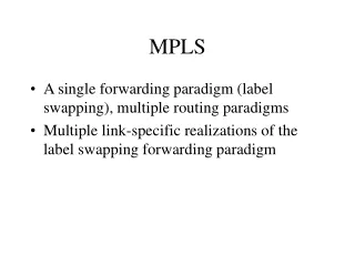
MPLS Overview • MPLS uses labels to forward traffic • Label values can be: • Assigned manually • Dynamically assigned using label distribution protocols • Label values are changed at each segment in the path • The LSR will remove the incoming label and replace it with an outgoing label as traffic traverses • Labels are only locally significant • The MPLS family must be enabled on an interface to send and receive MPLS packets
Label Distribution Protocols • LDP • Follows IGP best path • No traffic engineering • Allows extended discovery (LDP tunneling) • Allows traffic engineering to be applied to LDP traffic • Must enable lo0 in LDP on both ends of tunnel • Configured to signal over specific RSVP LSPs • RSVP • Allows for custom EROs • Allows traffic engineering • Administrative groups • Traffic protection • Priority and preemption • Bandwidth reservation
RSVP Path Selection • Default path selection • Uses the IGP to determine best path • Path manipulation using EROs • Define the path to signal LSPs • Path can contain strict hops, loose hops, or a combination • Strict hops specify the exact path • Loose hops use the IGP to route to the specified hop
Traffic Engineering Database • The traffic engineering database provides CSPF with up-to-date topology information • Contains network information • Current reservable bandwidth • Administrative groups • Populated by IGP advertisements • OSPF Type 10 LSA • IS-IS extended TLVs 22 and 135 • IGP must have traffic engineering enabled • OSPF requires additional configuration for traffic engineering • IS-IS has traffic engineering turned on by default
CSPF • The CSPF algorithm and traffic engineering database are used to calculate the best path to signal a RSVP LSP • CSPF combines the traffic engineering database with user constraints • Bandwidth requirements • EROs • Administrative groups • Prunes non-qualifying paths and performs SPF on remaining links • Does not span multi-area (OSPF) or multi-level (IS-IS) topologies • Can be turned off using the no-cspf option • Option available on a per-LSP or global basis
Administrative Groups • Administrative groups • Typically named with a color and assigned a 0-32 bit value • Names are locally significant • Only bit value is transmitted • Often referred to as link coloring • You can choose to include, exclude, or do nothing with links configured with a particular group name • If you include a named group, only those segments are selected • If you exclude a named group, all segments with that color are ignored during path selection • If you do nothing, the metric associated with the named group determines the path cost for that segment
Traffic Protection (1 of 2) • Multiple manual paths • Primary path (optional) • Revertive capabilities (default) • Secondary path (optional) • All secondary paths are equal (non-revertive) • Standby option pre-establishes the secondary path • Fast reroute • LSP builds detour paths • Temporary mechanism to reduce effects caused by a LSP failure • Requires CSPF on downstream routers • Detour paths immediately available • Configured on ingress router only • Does not honor bandwidth reservations
Traffic Protection (2 of 2) • Link protection • Creates a bypass LSP to protect a downstream link • Add link protection for the LSP on the ingress router • Add link protection on all downstream RSVP interfaces to be protected • Add user constraints to the bypass LSP like EROs, administrative groups, and bandwidth reservations • Node protection • Creates a bypass LSP to protect a downstream router • Add link-node protection for the LSP on the ingress router • Add link protection on the egress RSVP interface before the downstream router to be protected • Add user constraints to the bypass LSP like EROs, administrative groups, and bandwidth reservations
LSP Priorities and Preemption • Default priorities prevent preemption • Priority values range from 0 (strong) to 7 (weak) • Default setup priority is 7 • Default hold priority is 0 • High priority LSPs are signaled first • Hold priority must be equal to or stronger than setup priority
Bandwidth Reservation • Configured on a per RSVP LSP basis • Each router along the path verifies availability of the request • If any one router cannot support the requested bandwidth, the LSP creation will fail • No traffic policing by default with bandwidth reservations • Firewall policers can be used on the ingress router • The MPLS auto-policing option can be used on the ingress router
Automatic Bandwidth Provisioning • Network automatically adjusts bandwidth • Gathers statistics about LSP usage • Monitors usage every 300 seconds by default • Re-signals a LSP if necessary over a specified time frame • Default re-signaling interval is 24 hours • Uses make-before-break and shared explicit style reservations
Point-to-Multipoint LSPs • RSVP LSP with one ingress and multiple egress points • Packet replication happens when packets need to take two different paths (branches) • Branches can be added and removed without disrupting traffic • Branches can be configured statically, dynamically, or as a combination • Supports link protection (no fast-reroute)
LSP Authentication • RSVP • MD5 authentication available • Configured at the RSVP interface level • All RSVP messages are authenticated • LDP • MD5 authentication available • Configured at the session level • Applies to session messages only, not neighbor discovery • If authentication is applied to a established session, the session will reset and resignal
TTL Manipulation • Two options for TTL manipulation • no-decrement-ttl • Juniper Networks proprietary; all LSRs must support the option • RSVP support for individual LSPs or as global MPLS setting • No support for LDP • no-propagate-ttl • Global MPLS setting only • RSVP and LDP support this option • Allows for interoperability with other vendors
Route Table Integration and Policy Control • Only the LSP endpoint’s /32 address is added to inet.3 by default • Use the install option to add additional prefixes • Include the active option to allow the prefix to be installed and used in the inet.0 table • Policies can be used to control LSP selection • Apply as an export policy to the forwarding table • Use the action modifier that specifies the next-hop LSP to install for specific routes
MPLS Load Balancing • LSP traffic load balancing • Multiple equal-cost next hops over different interfaces to the same destination • Must create a policy to load balance • Must apply the load balancing as an export policy to the forwarding table • The load balancing hash algorithm can be altered to use the first MPLS label, the first two MPLS labels, the IP payload, or a combination of these options • Single next hop over an aggregated interface • Aggregated interfaces load balance traffic by default • The load balancing hash algorithm can be altered to use the first MPLS label, the first two MPLS labels, the IP payload, or a combination of these options
MPLS with BFD • RSVP • BFD is configured for a RSVP LSP on the ingress router • You can enable BFD for all LSPs or for specific LSPs • BFD sessions originate only at the ingress router and terminate at the egress router • LDP • You can enable BFD for the LDP LSPs associated with a specific FEC • You can configure an OAM ingress policy to enable BFD on a range of FEC addresses • Simple hello mechanism that detects failures in a network
MPLS Pitfalls (1 of 2) • RSVP • MPLS family required on the interfaces • Enabling correct interfaces in RSVP • Correct LSP names • LDP • MPLS family required on the interface • Correct interfaces in LDP • CSPF and the traffic engineering database • Does not work across multi-area or multi-level networks • Fast reroute, link or node protection, and administrative groups require CSPF
MPLS Pitfalls (2 of 2) • ERO • Using the loose transit point might result in an invalid path during network convergence • If two separate paths are required, ensure that you specify enough ERO hops to maintain separation • Fast reroute versus link or node protection • Understand the complete requirements of the task—fast reroute does not reserve bandwidth • Fast reroute creates a detour LSP • Link or node protection creates a bypass LSP
MPLS Time-Savers (1 of 2) • Before you begin configuring: • Read all tasks in the section • Plan your strategy for all tasks • Draw your LSPs on the topology • RSVP or LDP or both • Mentally group tasks that makes sense together • Simplify configuration steps • Use groups to apply the MPLS family to all similar interfaces • Cut and paste commands using the show | display set command • protocols mpls interface all • Remember to disable the management interface • Use interface all where possible
MPLS Time-Savers (2 of 2) • Take your time during the configuration phase • Avoids unnecessary troubleshooting • Make notes on topology • Verifying behavior • Take a structured approach by verifying key commands from one router at a time • Some verification commands can often be issued on a single device to determine behavior for multiple devices
Task and Topology • Task: • Create a RSVP LSP from R1 named r1-to-r9, that terminates on R9’s loopback. Ensure that this LSP reserves 2 Mbps of bandwidth across the network. You must also ensure that traffic entering the LSP is limited to the bandwidth reservation amount. All traffic in excess of the reserved bandwidth should be dropped without using a firewall policer. Loopbacks R1 – 192.168.1.1 R2 – 192.168.1.2 R3 – 192.168.1.3 R4 – 192.168.1.4 R5 – 192.168.1.5 R6 – 192.168.1.6 R7 – 192.168.1.7 R8 – 192.168.1.8 R9 – 192.168.1.9 Core MPLS Network C1-1 C3-2 R1 R3 Customer 3 R2 Customer 1 C2-2 C2-1 R4 Customer 2 Customer 2 R6 R5 C3-1 C1-2 Customer 3 Customer 1 R8 R7 R9
What Now? • What are the required components? • Connectivity • IGP route to egress router’s loopback • MPLS enabled on all interfaces • Interfaces added to the MPLS protocol • Interfaces added to the RSVP protocol • LSP configured that terminates on the egress router’s loopback • Bandwidth reservation applied to the LSP reserving 2 MB • All the LSPs path links must have at least 2 MB unreserved bandwidth • Apply the auto-policing option to the MPLS protocol
Task Completion (1 of 2) • Step 1: Initial verification • Verify connectivity • Verify interface • Verify protocol configuration lab@R1> show route 192.168.1.9 inet.0: 35 destinations, 35 routes (35 active, 0 holddown, 0 hidden) + = Active Route, - = Last Active, * = Both 192.168.1.9/32 *[OSPF/10] 00:16:56, metric 1 > to 172.27.0.9 via ge-0/0/1.0 [edit] lab@R1# show interfaces ge-0/0/1 unit 0 { family inet { address 172.27.0.14/30; } family mpls; } [edit] lab@R1# show protocols mpls interface all; [edit] lab@R1# show protocols rsvp interface all;
Task Completion (2 of 2) • Step 1: LSP configuration [edit protocols mpls] lab@R1# set label-switched-path r1-to-r9 to 192.168.1.9 bandwidth 2m [edit protocols mpls] lab@R1# set auto-policing class all drop [edit protocols mpls] lab@R1# show auto-policing { class all drop; } label-switched-path r1-to-r9 { to 192.168.1.9; bandwidth 2m; } interface all; [edit protocols mpls] lab@R1# commit and-quit commit complete Exiting configuration mode lab@R1>
Task Verification (1 of 2) • LSP verification lab@R1> show mpls lsp name r1-to-r9 detail Ingress LSP: 1 sessions 192.168.1.9 From: 192.168.1.1, State: Up, ActiveRoute: 0, LSPname: r1-to-r9 ActivePath: (primary) LSPtype: Static Configured LoadBalance: Random Encoding type: Packet, Switching type: Packet, GPID: IPv4 *Primary State: Up Priorities: 7 0 Bandwidth: 2Mbps SmartOptimizeTimer: 180 Computed ERO (S [L] denotes strict [loose] hops): (CSPF metric: 1) 172.27.0.9 S 172.27.0.22 S Received RRO (ProtectionFlag 1=Available 2=InUse 4=B/W 8=Node 10=SoftPreempt 20=Node-ID): 172.27.0.9 172.27.0.22 Total 1 displayed, Up 1, Down 0 ...
Task Verification (2 of 2) • Reservation verification • Policer verification lab@R1> show rsvp interface RSVP interface: 7 active Active Subscr- Static Available Reserved Highwater Interface State resv iption BW BW BW mark ge-0/0/1.0 Up 1 100% 1000Mbps 998Mbps 2Mbps 2Mbps ... lab@R1> show interfaces ge-0/0/1 extensive | match "output bytes" Output bytes : 1539377364 2103304 bps Output bytes : 1524736484 Output bytes : 31435434 Output bytes : 1493301050 2102392 bps