Download
1 / 16
160 likes | 342 Vues
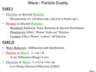
Plane Wave Echo Particle Image Velocimetry. Samuel Rodriguez, Xavier Jacob, Vincent Gibiat PHASE University Paul Sabatier. Basics of topological optimization applied to acoustic waves. Plane Wave Echo Particle Image Velocimetry.

E N D
Plane Wave Echo Particle Image Velocimetry Samuel Rodriguez, Xavier Jacob, Vincent Gibiat PHASE University Paul Sabatier
Basics of topologicaloptimizationapplied to acousticwaves Plane Wave Echo ParticleImage Velocimetry Basics of topological optimisation applied to acousticwaves • Topological optimisation: optimisation of a physicaldomain for a given set of loads and boundaries • Numerical applications for electromagnetic and ultrasonicimaging [Pommier and Samet, Bonnet, Malcolm and Guzina, Dominguez and Gibiat, SahuguetChouippe and Gibiat] • An experimental application with a transducerarray: the TDTE method [Dominguez and Gibiat, DominguezGibiat and Esquerre]. Use of a time-domainfinite-difference model. • The FastTopological Imaging methodis an adaptation in the frequencydomain of the TDTE methodthataimsatreducing the computation cost. S. Rodriguez, X. Jacob, V. Gibiat
Basics of topologicaloptimizationapplied to acousticwaves Plane Wave Echo ParticleImage Velocimetry • Topological optimization Initial domain Parameterization Shape optimization Topological optimization Figure adapted from [J. Pommier, “L’asymptotiquetopologique en electromagnétisme”, PhD thesis] S. Rodriguez, X. Jacob, V. Gibiat
Basics of topologicaloptimizationapplied to acousticwaves Plane Wave Echo ParticleImage Velocimetry • Topological optimization Solution without a “hole” Cost Calculation of the gradient Solution with a “hole” Cost Figure adapted from [J. Pommier, “L’asymptotiquetopologique en electromagnétisme”, PhD thesis] S. Rodriguez, X. Jacob, V. Gibiat
Basics of topologicaloptimizationapplied to acousticwaves Plane Wave Echo ParticleImage Velocimetry Referencee Inspected Med. 0 0 m ? (um-u)( ,t) u( ,t) um( ,t) Adjoint Prob. v( ,t) Adjoint (um-u)(,T-t) 1- Echographicmeasure of um(r,t) 2- Numerical computation of the referencefield and measureofu(r,t) 3- Differencebetweenref and inspected then time reversal to compute 4- the adjoint fieldv(r,t) Calcul of topologicalderivative in time domain S. Rodriguez, X. Jacob, V. Gibiat
Experimentalstaticresults Plane Wave Echo ParticleImage Velocimetry How does it work in “true life” • Experimental conditions • 32-transducer array. Resonance freq 5 MHz. 0.8 mm pitch. • Lecoeur OPEN system 80 MHz. • Plane wave. 3-period sinus. Transducerarray Water Time Array Gelatin cylinder
Experimentalstaticresults Plane Wave Echo ParticleImage Velocimetry How to take into account the geometry and the radiation of the transducers? How to compute efficiently (fast and accurate) the direct and adjoint fields ? A solution is to transpose the time domain to the frequency one TDTE versus FTIM S. Rodriguez, X. Jacob, V. Gibiat
Experimentalstaticresults Plane Wave Echo ParticleImage Velocimetry • we have the physical information that comes from : • The experimental data: • Dimensions of the transducers and a theoretical or a numerical model (as near as possible from the reality) of the wave propagation in the medium 1 ) Computation of the radiation patterns of every transducer j and every frequency : FT signal emitted by transducer j FT signal measuredwithtransducer j Transducer COMPUTED ONCE AND FOR ALL
Experimentalstaticresults Plane Wave Echo ParticleImage Velocimetry 2. Computation of the solutions with simple multiplications (time-domain convolutions) : Transducerarray Transducerarray X X + X +
Experimentalstaticresults Plane Wave Echo ParticleImage Velocimetry 3. Computation of the topological derivative of the FTIM method Transducer array Transducer array Envelope of RF signals FTIM Time Depth
Experimentalstaticresults Plane Wave Echo ParticleImage Velocimetry Application to an anisotropicsolid medium • Composite materialsample • Radiation patterns computedwith a FE model. TDTE FTIM² 100 TIMES FASTER
Experimentaldynamicresults Plane Wave Echo ParticleImage Velocimetry Small water tank Put marble powder « beatite from Saint Béat » Let the bigger particles sediment Particles smaller than 40 micrometers (invisible) remain in water Insonification from the bottom Image of a slice of the water tank S. Rodriguez, X. Jacob, V. Gibiat
Experimentaldynamicresults Plane Wave Echo ParticleImage Velocimetry Sedimentation of marble powder Water level Top Bottom S. Rodriguez, X. Jacob, V. Gibiat
Experimentaldynamicresults Plane Wave Echo ParticleImage Velocimetry Passage of a single wave at the water surface Water level Top The interface water/air acts as a mirror S. Rodriguez, X. Jacob, V. Gibiat
Experimentaldynamicresults Plane Wave Echo ParticleImage Velocimetry Water rotated with a magnetic agitator and seeded with small particles (about 40 micrometer big), mimicking contrast agents. PRF=250 images/s, and horizontal insonification video_vortex_flow S. Rodriguez, X. Jacob, V. Gibiat
Plane Wave Echo ParticleImage Velocimetry Conclusion Instead of Time Domain Topological Energy (10 minutes/image) Frequency Domain alternative is possible (FTIM) (6 seconds/image) Through FTIM algorithm it is possible to record sequences at frequency varying between 250 Hz and 1000 kHz to derive dynamic ultrasonic images of moving very small particles Everywhere such “reflecting” objects exist it is possible to image Their movements FTIM is a credible alternative to PIV each time it is not possible to optically Illuminate the medium S. Rodriguez, X. Jacob, V. Gibiat