Neutron Wall Loading Profile Calculation Using CAD/MCNP Interface in Compact Stellarator Design
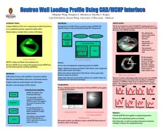
This study explores the first application of a CAD-MCNP coupling approach to compute neutron wall loading distributions in the ARIES-CS Compact Stellarator design. The calculations reveal an average neutron loading of 1.985 MW/m² and a peak of 3.24 MW/m² occurring at a 0-7.5-degree outbound section, with a relative error of 9%-10%. By utilizing CAD for geometry modeling, the study demonstrates advantages in managing the complex geometries required for accurate nuclear analysis and highlights the future potential for improving computational speed.

Neutron Wall Loading Profile Calculation Using CAD/MCNP Interface in Compact Stellarator Design
E N D
Presentation Transcript
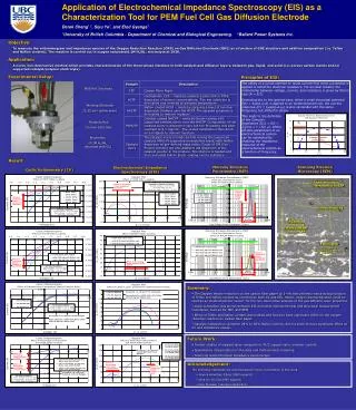
Neutron Wall Loading Profile Using CAD/MCNP Interface Mengkuo Wang, Douglass L. Henderson, Timothy J. Tautges, Laila El-Guebaly, Xueren Wang, University of Wisconsin – Madison APPLICATION: The first real application of the CAD-MCNP coupling approach is to calculate the neutron wall loading distribution (Γ) in the Z and toroidal directions of the ARIES-CS design. Subdivision of CS model Tally portion of CS model There are 8 neutron wall loading profiles in this portion. For 1600MW of total neutron power, the average neutron loading is 1.985MW/m² and peak is 3.24MW/m² which occurs at outbound of 0-7.5 degree portion. The computation takes 5 days at a linux station and relative error is about 9%-10%. INTRODUCTION: Compact Stellarator (CS) is for a commercial power plant fusion device. It is a complicated geometry composed by spline surface. Nuclear analysis is needed. Such as neutron wall loading. Compact Stellarator MCNP is widely used Monte Carlo simulation tool. However, MCNP can not construct this geometry because MCNP only provides limited geometry modeling capalibilities. METHODS: Our approach: Use CAD software as geometry engine of MCNP. The radiation transport is directly performed through the CAD geometry. CAD based MCNP approach Benefits: Save the time of modeling the complicated geometry for MCNP. Support all kinds of geometry provided by CAD software. Such as high order surface, spline surface, facet surface. Obtain some advance features from CAD software. Such as gap/overlap detection, surface area function. Update easily. The most recent geometry functions are available which will be updated by the CAD software developer. We subdivide the plasma in horizontal and toroidal direction. The toroidal subdivision is 7.5 degree each. The horizontal subdivision is 0.5 m each. CAD (CUBIT) CAD geometry file Physics input file Geometry engine (CGM) CAD based MCNP CAD geometry engine (CGM) MCNP Ray object intersection 60 By the symmetry, we select portion from 0 to 60 degree toroidally to tally. The other symmetry patch was combined to this portion to reduce relative error. 0 METHODS: CAD software focuses on the capabilities of geometry modeling. They have powerful abilities and provide a user-friendly interface. Complex models are usually designed with CAD systems. Then how to take advantage of CAD software? Converter approach VALIDATION: We use a clothespin model to demonstrate CAD based MCNP can be applied to complicated geometries. (a) Shown by CAD (b) Radiation image simulated by CAD based MCNP Clothespin model This model would be very difficult to analyze with MCNP alone because of the helical surface of the spring. • Converter is not a good idea. • MCNP still supports only limited geometry type. • It is impossible to 100% convert a CAD geometry to MCNP because CAD supports more types of geometry than MCNP. • If using approximation to convert a CAD model, it is hard to decide how to make approximation. • Once there is a new geometry type in CAD software, we need to update the converter to support new type. CAD file Converter Input file Summary: CAD based MCNP can be applied to complicated geometries. However, the computational speed is not satisfied. In the future plan, we will use ray-object intersection acceleration techniques to improve the computational speed. MCNP