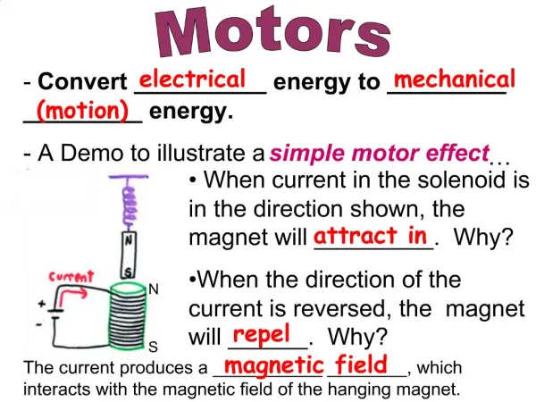
Controlling Motors
Controlling Motors. OBEY ME!. On-Off Control. 1. Switch control. HIGH (+5V). LOW (0V). 2. Transistor control. Pin 2. GND. Several motors. GND. Watch out for TIP120 overheating. Several motors, each controlled. GND. Several batteries. GND. MOSFET Control. DRAIN (D). GATE (G).

Controlling Motors
E N D
Presentation Transcript
Controlling Motors OBEY ME!
HIGH (+5V) LOW (0V) 2. Transistor control
Pin 2 GND
Several motors GND Watch out for TIP120 overheating
MOSFET Control DRAIN (D) GATE (G) SOURCE (S) GND
Ids S D G D Rds on S MOSFET IRL520 Max current = 10 A Rds on = 0.18 ohm If motor draws 2.0 A Vds = I*R = 2.0*.18 = .36V P = IV = 2*.36 = .72W For TIP120, Vce = 1.5V P = 2*1.5 = 3W !
I I Rds on For high currents, bipolar wins P MOSFET P = I2Rds ~ I2 BIPOLAR P = VceI ~ I I
MOSFET Parts Rdson = 0.180 ohm $0.50 Rdson = 0.0037 ohm $1.50
3. Relay control • Relays good for high current motors • Watch out for relay coil drain 12V relay GND TIP120 or 2N3904
Bi-directional motor control 12V DPDTRELAY CCW "DIRECTION" CW "ON-OFF" TIP120 or IRL520 or RELAY GND
Bi-directional motor control with L293D $2.00 ~600 mA limit See www.me.umn.edu/courses/me2011/arduino/technotes/dcmotors/L293/L293.html
V I t BIG SPIKE ! Inductive loads cause switching spikes L V I GND
- + diode Noise Spike Suppression .47, 100V mylar
Slowing Motor With a Power Resistor 10-15 ohmpower resistor3W+ Need a load resistor?Try a flashlight bulb, or a second motor
12 12 12 12 V V V V 0 0 0 0 Control Speed by Pulse Width Modulation (PWM) Vavg = 12 V 100% Vavg = 6 V 50% Vavg = 3 V 25% Open and close switch rapidly 0% Vavg = 0 V
PWM for Variable Speed ... while(digitalRead(6)==HIGH) { digitalWrite(11,HIGH); delay(5); digitalWrite(11,LOW); delay(35); } ... Duty cycle = 5/40 = 12.5% Watch out for voltage spikes! ... //run at 3 speeds analogWrite(11,64); //slow delay(2000); analogWrite(11,128); //medium delay(2000); analogWrite(11,255); //fast delay(2000); ... Arduino analogWrite PWM valid on pins 3, 5, 6, 9, 10, 11
Remember When motor runs slower, torque is less
Detect Position with a Switch • Code • Motor on • Wait for switch closed • Motor off
Detect Position with a Potentiometer • Output voltage varies between 0 and 5V as angle changes • Read with analogRead() function,www.arduino.cc/en/Reference/AnalogRead
Stepper Motor • One pulse per step • 48, 100, 200 steps/rev common • Send to precise position by a set # of pulses • If high torque disturbance can be bumped out of holding detent • 4 Arduino pins • ULN2003A interface driver or 4 transistors • See stepper motor section at https://sites.google.com/a/umn.edu/me2011/arduino
Servo Motor • Gearmotor with internal position feedback and internal controller • Control position with continuous pulse stream; width of pulse determines position • Typical range: 90 to 180 degrees • Common in hobby robotics; primary application from RC airplanes • Can modify for continuous rotation • See servo motor section at https://sites.google.com/a/umn.edu/me2011/arduino