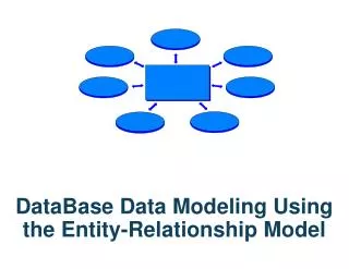
Constructing a Conceptual Schema: Introduction to Entity-Relationship Modeling
This chapter explores the fundamentals of Entity-Relationship (E-R) modeling, focusing on how to construct a conceptual schema. It defines key concepts such as entities, attributes, and relationships, along with the significance of identifiers and primary keys. The chapter emphasizes the importance of well-defined relationships and discusses cardinality and maximum cardinality in E-R diagrams. Additionally, it differentiates between weak and strong entities, illustrating their characteristics with examples. Visualization techniques, including crow's foot notation, are introduced for representing relationships effectively.

Constructing a Conceptual Schema: Introduction to Entity-Relationship Modeling
E N D
Presentation Transcript
Entity-Relationship (E-R) modeling: constructing a conceptual schema (Chapter 5) • Due to course constraints I have to defer other modeling issues (normalization in chapters 3 and 4) until later in the semester.
Entity • a thing you need to model. • It is analogous to a class in object oriented design. • Fields of an entity are called attributes. • An entity instance is an occurrence of a particular entity. • It is analogous to an object. However, there is no encapsulation in the OO sense.
One or more attributes is usually an identifier, which uniquely identifies an entity. • It is also called a key, though the term identifier is used in the data model and key is used when creating tables. • Semantics.
Design issue: • Many designers like to keep each identifier and primary key dataless • This means that it contains no information about the entity. This way, they never change. • Ex. IDs, account numbers, etc.
Advantageous if there’s an index or hash function that uses the keys since a changing key would change the internal structure. • Also useful since a key value sometimes exists in other records that are related to the entity with the given key. • These would need to change also.
A relationship defines how two or more entities are connected according the rules in the reality you are modeling.
Some guidelines • A relationship should be named and well-defined. • Do not simply state there is a relationship between two entities. • Articulate what the relationship represents.
Example: • there is a relationship between a student entity and a course entity. • So? • Does it represent courses for which the student has registered? • Does it represent courses dropped? • Does it represent courses needed for a major? • Does it represent courses on a transcript? • Spell it out!!
Degree of a relationship is the number of entities involved. • Most are degree 2 (binary relationships) but some are more. • A ternary relationship involves 3 entities. Example: p. 148. • Can you think of more?
Cardinality is the number of entity instances in a relationship. • Maximum cardinality is the maximum number of instances in a relationship. • For example, the relationship between a sports team and its players has a maximum cardinality defined by rules of the sport.
Three types of maximum cardinality • 1-1 relationship between A and B • For each instance of type A there is no more than one instance of type B, and vice-versa. • Notation and example: p. 149
Some possible examples: • Employee fleet vehicle • Project employee (defined by who is project leader and assumes each employee leads no more than one project.) • Employee computer 1:1 1:1 1:1
1-many relationship between A and B • For each instance of type A there may be many instances of type B; however, for each instance of type B there is no more than one instance of type A. • Notation and example: p. 149.
Other possible examples: • Coursesections • Departmentsemployees • projectemployees (participation) • Employeecomputer 1:N 1:N 1:N 1:N
May actually specify a maximum number. • Example: Team-players. Number depends on the sport. • Sometimes the term parentapplies to the entity on the “one side” and child applies to the entity on the “many side”.
Many-many relationship between A and B • For each instance of type A there may be many instances of type B, and vice-versa. Notation: p. 149 • More examples follow
Studentscourses (could have several meanings) • Authorsbooks • Moviesactors; • advisorsstudents; • artistsongs • Majorcourses N:M N:M N:M N:M N:M N:M
These are sometimes called HAS-A relationships. • A team has players; a student has courses; etc.
Minimum cardinality • May specify a minimum number of instances. • Can specify whether an instance is mandatory or optional. • Examples: p. 150. Can you think of more?
A crow’s foot notation (page 152-153) often used to provide a visual of the relationships. • We’ll use this notation in subsequent diagrams
Weak entity • Cannot exist unless another type of entity exists • Employeedependent (dependent is weak) • building room (room is weak) • course section (section is weak) • book has more
ID-dependent entity • special type of weak entity in which the ID contains the ID of another entity • EX: Rooms on campus have an ID such as MAC 122 (Building ID and room number). • Other examples on page 154 • All ID-dependent entities are weak • A weak entity may not be ID-dependent (example p.155)
Shown in diagram using solid lines (ex. P.154) • If the parent entity is removed, so must all child entities. • Dashed lines represent non-identifying relationships
Strong entity • existence does not depend on another entity. • Ex: Students, employees, departments, computer, building, etc.
Difference between strong and weak not always clear. • Subject to variances in interpretation of the mode. • Kroenke lists possible tests on page 156 and 160
Example: • One-to-many relationship between a pharmaceutical company and a drug. • One-to-many relationship between an employee and a dependent. • Dependent does not exist w/o the employee. • Drug does not exist w/o the pharmaceutical company • Are drug and dependent both weak?
If the employee is removed the dependent disappears. • If the pharmaceutical company disappears, the drug may be assigned to another company. • Argues that the drug is strong.
Creating an E-R diagram using Visio: • Open Microsoft Office Visio. • Select Software and Database under template categories. • Select Database Model Diagram as a template. • Press the Create button. • Drag and drop one or more entity images to your worksheet.
Double click on the icon and, through the properties pane below the worksheet, you can give it a name and define its fields. • Drag and drop a relationship icon to the worksheet. • Connect each end to an entity.
To get the “crow’s foot” format • select Display Options in the database tab • Select the Relationship tab • check the Crow’s feet checkbox. • Double click the relationship icon • select miscellaneous under categories • Select the appropriate cardinality.
NOTE: Visio does not allow the specification of a many-to-many relationship. • Does a poor job as a modeling tool. • However, we will see later that ALL many-to-many relationships can be implemented via two one-to-many relationships
Probably best to NOT use visio for true data modeling diagrams. • But OK for defining relationships among tables and for this course.
n:m n:m Ternary relationships. • Doctor – Patients – Drugs • Relationship below does not convey all necessary information patient drug doctor drug prescription prescribes
patient doctor drugs • A specific drug given to a patient must have been prescribed by a doctor. • Would need
Building a data model: • Interview the users of data. Find out how they operate!! • Look at existing forms, reports, files, lists, etc. • Determine entities. Look for key words such as order, appointment, product, customer, etc.
Specify relationships. • Examine all combinations of entities or examine documents obtained from previous steps. • Determine what attribute (identifier) uniquely determines an entity.
Determine attributes. • Ask whether an attribute should be its own entity. • Salesperson has a region: should region be just an attribute or a separate entity? • Data models should reflect reality. • Problem is one person’s reality may be different than another’s.
In Class example: Design a data model for a university database.
Using Patterns to design relationships. • Asking users what the maximum cardinality is won’t work • they won’t know what you’re talking about. • You can show them a prototype form or report to learn how many entity objects relate to another. • Ex. Show a course form to a user that shows one instructor. • The user will likely let you know if other instructors should be shown.
Figure 5-15a on p. 159 • Suggests a 1-1 relationship between strong entities member and locker • Data model in Figure 5-16
Figure 5-17 on p. 160 • Suggests a one-to-many between company and department • Figure 5-18 shows the model
Figures 5-19a and 5-19b on p. 161 • The form and report suggest a many-to-many relationship between company and part • Data model in Figure 5.20
Association pattern: • Consider a n:m relationship connecting students and courses (transcript). • Where is the grade stored? • It is not part of the student entity • It is not part of the course entity.
The data model should show a 3rd entity (transcript?) containing the grade • This is analogous to the example from figures 5.21 & 5.22 on p. 162-163
Multivalued attribute pattern • when is an attribute not an attribute • Consider a customer entity. • Is the phone number an attribute? • If just one number, store as an attribute. • If multiple numbers, might be a problem since arrays or lists can not be attribute types in a relation.
May create an ID-dependent entity, PHONE, connected to the customer. • If just two numbers max, might create a primary and secondary phone number attribute of the customer.
Archetype/Instance pattern • One entity represents an instance of another. • Prints of a painting • Copies of a book • Sections of a course
Line Item Pattern • Multiple instances of an entity used to describe another entity • Ex: Line items to describe an order
Recursive relationships – may be 1:1, 1:n, or n:m • A course and it’s prerequisites (n:m). • A course may have multiple prerequisites and may be a prerequisite for multiple other courses. • Manufacturing (Bill of Materials). • Products consists of parts, some of which are composed of other parts. • Parts may be included in other parts (p. 173)