Wireless Phone Tic-Tac-Toe
This project demonstrates interfacing wireless phones with hardware using DTMF signals for a time-insensitive Tic-Tac-Toe game. Players take turns pressing buttons 1-9; their tones are detected and relayed via DTMF decoders. The HC12 processes these signals, sending acknowledgment and checking for winning sequences via LED displays. A 3x3 bi-color LED array represents the game board, controlled using shift registers to optimize pin usage. The project outlines both the operational and algorithmic aspects, ensuring fluid gaming experience despite transmission delays.


Wireless Phone Tic-Tac-Toe
E N D
Presentation Transcript
Wireless Phone Tic-Tac-Toe Josh Morelli
Project Description • The purpose is to illustrate the interfacing of hardware and wireless phones using standard Dual-Tone Multi-Frequency (DTMF) signals. • Because of delays associated with wireless phone transmissions, a time-insensitive project was necessary. • Hence, Tic-Tac-Toe.
Operational Description • Player A presses a button 1-9. • Player B’s phone receives the tone and sends it to the DTMF decoder through the 2.5mm headset jack. • Player A’s phone does the same thing simultaneously • Decoder outputs a 4-bit representation of button pressed to the HC12
Operational Description (cont) • HC12 immediately sends the same signal to a DTMF generator • Generator sends identical tone back to Player A for acknowledgement (ACK) • Once ACK is verified, HC12 processes the signal and illuminates the appropriate LED on the display board
Operational Description (cont) • HC12 then processes a simple algorithm to determine if a winning sequence has been lit • If a winner is found, the winning sequence of LED’s is flashed • Play continues until a winner is found, or reset button is pressed
Algorithm Description • First checks one diagonal and all horizontal possibilities, then rotates pattern 90 degrees to check other diagonal and vertical possibilities.
Algorithm Description (cont) • HC12 will logically re-order board positions for pattern recognition. New order will allow rotation simply by bit-shifting one 8-bit register. Original Re-ordered Rotated
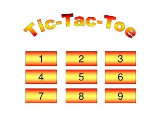
Display Board • The display board will be the primary output component of the user interface. • A 3x3 array of bi-color (red/green), three-leaded LED’s will be used to represent the traditional X’s and O’s.
Display Board (cont) • The LED array will be controlled by two 16-bit serial shift registers (74LS673) to reduce the number of HC12 pins used. • Two 10-bit high-output buffers (TI P/N SN74ABT827) will provide the driving current for the LED array. • Each LED will have a voltage divider attached to each of its 2 anodes to control proper voltages and currents.
DTMF Decoder • 18-pin DIP IC (TDK P/N: TSC 75T202) • No input signal filtering required • 4-bit output, binary representation of 12 possible standard phone buttons • Uses a common, inexpensive reference crystal (3.579545 MHz)
DTMF Generator • 16-pin DIP IC (TI P/N: TCM5089) • 4-bit row, 4-bit column input, combined to select output frequencies • Output frequency error is ≤0.73% • Also uses the 3.579545 MHz crystal