Download
1 / 40
400 likes | 429 Vues
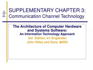
The Architecture of Computer Hardware and Systems Software: An Information Technology Approach 3rd Edition, Irv Englander John Wiley and Sons 2003. SUPPLEMENTARY CHAPTER 3: Communication Channel Technology. Communication Channel. Communication Channels: Many Ways to Implement.

E N D
The Architecture of Computer Hardware and Systems Software: An Information Technology Approach 3rd Edition, Irv Englander John Wiley and Sons 2003 SUPPLEMENTARY CHAPTER 3:Communication Channel Technology
Communication Channel Supplementary Chapter 3Communication Channel Technology
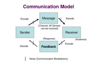
Communication Channels:Many Ways to Implement • Signal: specific data transmitted • Diagram shows communication between computer and a wireless laptop • Deceptively simple: phone line carries electrical representation of audio signal • Physically: signal passes through different channel forms including audio, digital, light, radio • Converters between separate physical channels Supplementary Chapter 3Communication Channel Technology
Communication Channel • Characterized by • Signaling transmission method • Bandwidth: amount of data transmitted in a fixed amount of time • Direction(s) in which signal can flow • Noise, attenuation, and distortion characteristics • Medium used Supplementary Chapter 3Communication Channel Technology
Signaling Transmission Method • Analog: continuous varying waveforms to carry data • Digital: • Two different values of electrical voltage or current or • On/off light source • Frequently preferred because less susceptible to noise and interference Supplementary Chapter 3Communication Channel Technology
Channel Organization • Point to point channels • Simplex: channel passes data in one direction only • Half-duplex: transmits data one direction at a time (walkie-talkie) • Full-duplex: transmits data in both directions simultaneously (telephone) • Multipoint: broadcasts messages to all connected receivers Supplementary Chapter 3Communication Channel Technology
Multiplexing • Carrying multiple messages over a channel simultaneously • TDM (time division multiplexing) • Example: packet switching on the Internet • Use: digital channels • FDM (frequency division multiplexing) • Example: Cable TV • Analog channels • Filters separate different data signals at receiving end Supplementary Chapter 3Communication Channel Technology
Signaling Technology • Carrier waves • Electrical voltage • Electromagnetic radio wave • Switched light • Data represented by changes in the signal as a function of time • Range of values • Analog: continuous values • Discrete: countable number of possible values • Digital: binary discrete signal Supplementary Chapter 3Communication Channel Technology
Waveform • Representation of a signal shown as a function of time Supplementary Chapter 3Communication Channel Technology
Communicating between Digital and Analog • Ideally conversion should be reversible • Limited by • Noise: interference from sources like radio waves, electrical wires, and bad connections that alter the data • Attenuation: normal reduction in signal strength during transmission caused by the transmission medium • Distortion: alteration in the data signal caused by the communication channel • Consequences • Error correction required to compensate for transmission limitations • Usually possible to recover original digital data exactly from analog transmission • Small information loss results from converting analog to digital Supplementary Chapter 3Communication Channel Technology
Analog Signals • Wireless networking • Most telephones • Satellites • Microwave communications • Radio and sound • Radio waves can be converted to electrical signals for use with wire media for mixed digital and analog data • Example: Cable TV with digital Internet feed Supplementary Chapter 3Communication Channel Technology
Sine Wave • Common natural occurrence • Basic unit of analog transmission • Amplitude: wave height or power • Period: amount of time to trace one complete cycle of the wave • Frequency: cycles per second, i.e., number of times sine wave repeated per second f = 1/T where T is the period measured in seconds Supplementary Chapter 3Communication Channel Technology
Hertz • Measure of frequency • 1 Hertz = 1 cycle/sec • Unit of bandwidth for analog device • Frequency of sine wave in diagram: 4Hz Supplementary Chapter 3Communication Channel Technology
Circle and the Sine Wave • Points on a sine wave frequently designated in degrees • v = A sin[Θ] where A is the maximum amplitude and Θ is the angle in the diagram Supplementary Chapter 3Communication Channel Technology
Phase • Difference, measured in degrees, from a reference sine wave Supplementary Chapter 3Communication Channel Technology
Waveform Representation • All can be represented as the sum of sine waves of different frequencies, phases, and amplitudes • Spectrum: frequencies that make up a signal • Bandwidth: range of frequencies passed by the channel with a small amount of attenuation • Filtering: controlling the channel bandwidth to prevent interference from other signals Supplementary Chapter 3Communication Channel Technology
Signal Frequencies • Sound waves: approximately 20 Hz to 20 KHz • Stereo systems: 20-20,000 Hz for high fidelity • Phones: 0-4000 Hz for voice but limits speed • Electromagnetic radio waves: 60 Hz to 300 GHz • AM radio: 550 KHz to 1.6 MHz • 20 KHz bandwidth centered around dial frequency of the station • FM radio: 88 MHz to 108 MHz • 100 KHz bandwidth per station • TV: 54 MHz to 700 MHz • >4.5 MHz bandwidth per channel • Cellular phones: around 900 MHz Supplementary Chapter 3Communication Channel Technology
Signal Frequencies Supplementary Chapter 3Communication Channel Technology
Sine Waves as Carriers • A single pure tone consists of a sine wave • The note A is a440-Hz sine wave • To represent the signal modulate one of the three characteristics – amplitude, frequency, phase • Example: AM or amplitude modulated radio station at 1100 KHz modulates amplitude of the 1100 KHz sine wave carrier • TV • Amplitude modulation for the picture • Frequency modulation of the sound • Phase modulation for the color • Demodulator or detector restores original waveform Supplementary Chapter 3Communication Channel Technology
Amplitude Modulations Supplementary Chapter 3Communication Channel Technology
Modulating Digital Signals • Two possible values: 0 and 1 • 3 techniques • ASK: amplitude shift keying • Represents data by holding the frequency constant while varying the amplitude • FSK: frequency shift keying • Represents data by holding the amplitude constant while varying the frequency • PSK: phase shift keying • Represents data by an instantaneous shift in the phase or a switching between two signals of different phases Supplementary Chapter 3Communication Channel Technology
Modulating Digital Signals Supplementary Chapter 3Communication Channel Technology
Attenuation • Function of the nature of the transmission medium and the physical length of the channel • More difficult to separate the signal from noise at higher transmission speeds • Signal-to-noise ratio: • Strength of the signal in relation to power of the noise • Measure at the receiving end • Amplifiers: restore original strength of the signal Supplementary Chapter 3Communication Channel Technology
Effects of Attenuation • Channel fading and phase shifts vary with the frequency of the signal • Example: If the signal consists of sine waves of frequencies f1 and f2 from different parts of the spectrum, the output of the channel will be distorted Supplementary Chapter 3Communication Channel Technology
Synchronizing Digital Signals • Synchronizing digital signals difficult • Asynchronous transmission • Clear start and stop signals • Small number of bits, usually one byte • Use: low-speed modems • Synchronous transmission • Continuous digital signal • Use: high-speed modems and point-to-point methods Supplementary Chapter 3Communication Channel Technology
Reception Errors • Timing mismatch between sending and receiving computers Supplementary Chapter 3Communication Channel Technology
A-to-D Conversion • Digital signals used to represent analog waveforms • Examples: CDs, direct satellite TV, telephone voice mail Supplementary Chapter 3Communication Channel Technology
A-to-D: Pulse Code Modulation • Analog waveform sampled at regular time intervals • Maximum amplitude divided into intervals • Example: 256 levels requires 8 bits/sample Supplementary Chapter 3Communication Channel Technology
A-to-D: Pulse Code Modulation • Sample values converted into corresponding number value • Information lost in conversion Supplementary Chapter 3Communication Channel Technology
A-to-D: Pulse Code Modulation • Number reduced to binary equivalent Supplementary Chapter 3Communication Channel Technology
Digital Signal Quality • Subject to noise, attenuation, distortion like analog but • Signal quality less affected because only necessary to distinguish 2 levels • Repeaters • Recreate signals at intervals • Use: transmit signals over long distances • Error correction techniques available Supplementary Chapter 3Communication Channel Technology
TDM • Time division multiplexing • Multiple signals share channel Supplementary Chapter 3Communication Channel Technology
Bandwidth • Digital signals: sum of sine waves of different frequencies • Higher frequencies: higher data rates • Channel with wider bandwidth has higher data rates • Data rates usually measured in bits per second Supplementary Chapter 3Communication Channel Technology
Modems and Codecs • Modem (modulator/demodulator) • Convert digital signals to analog and back • Use: home to service provider via phone line or cable • Speed: baud rate or bits per second (bps) • Baud rate: signaling elements per second • At slow speeds 1 bit encoded per electrical signal • Higher speed transmissions usually measured in bits per second rather than baud rate • High speed modem: • 28.8 Kbps access with ASK, FSK and PSK • 56 Kbps download with wider bandwidth at telephone switching office Supplementary Chapter 3Communication Channel Technology
Codecs • Codec (coder/decoder) • Use: DSL (Digital Subscriber Line) via digital phone lines or cable • Ethernet for connection between the codec and the computer • Speed: 1Mbps or higher Supplementary Chapter 3Communication Channel Technology
Transmission Media • Means used to carry signal • Characterized by • Physical properties Bandwidth • Signaling method(s) Sensitivity to noise • Guided media: confine signal physically to some kind of cable • Unguided media: broadcast openly • Signal-to-noise ratio • Higher ratio for given bandwidth increases data capacity of the channel Supplementary Chapter 3Communication Channel Technology
Electrical Media • Require complete circuit • 2 wires: one to carry the signal, second as a return to complete the circuit • Wired media or just wire • Inexpensive and easy to use • Signals carried as changing electrical voltage or current Supplementary Chapter 3Communication Channel Technology
Types of Cable: Copper • Coaxial cable • Wire surrounded by insulation • Copper shield around insulation • Acts as signal return • Shields from external noise • High bandwidth: 100 Mbps • Example: analog cable TV with FDM for dozens of channels at 6 MHz • Twisted pair • Some networks and phone lines in buildings • More susceptible to noise than coaxial cable • Used for shorter distances and slower signals Supplementary Chapter 3Communication Channel Technology
Types of Cable: Fiber Optic • Fiber optic cable • Consists of glass fiber thinner than human hair • Uses light to carry signals • Laser or light-emitting diode produces signal • Cladding: plastic sheath to protect fibers • Advantages • Light waves: high frequency means high bandwidth • Less susceptible to interference • Lighter than copper cable • Disadvantages • Difficult to use, especially for multipoint connections Supplementary Chapter 3Communication Channel Technology
Microwave • Frequencies below light • Unguided medium • Tightly focused for point-to-point use • Highly susceptible to interference • Applications • Large-scale Internet backbone channels • Direct satellite-to-home TV • IEEE 802.11 Wi-Fi Supplementary Chapter 3Communication Channel Technology