Understanding the Electronic Voting Machine (EVM) – A Comprehensive Overview
This presentation, by Miss Kenyir Olga Nongrum from the Election Department Jowai, explores the Electronic Voting Machine (EVM) as a reliable tool for conducting elections. It details its two main units: the Ballot Unit and Control Unit, designed for ease of use and portability. The EVM features tamper-proof technology, operates on a specialized battery, and retains recorded information even when powered off. Learn about its functionality, components, and vital details necessary for effective voting processes.

Understanding the Electronic Voting Machine (EVM) – A Comprehensive Overview
E N D
Presentation Transcript
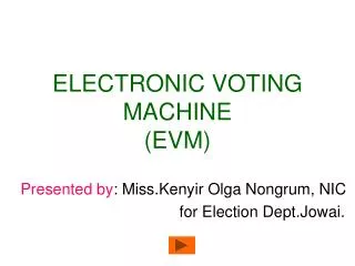
ELECTRONIC VOTING MACHINE(EVM) Presented by: Miss.Kenyir Olga Nongrum, NIC for Election Dept.Jowai.
Introduction to EVM • It is a reliable machine for conducting Elections. • Has mainly 2 units: Ballot and Control Units. • Operates on a Special Battery • Tamper-proof • Information recorded is retained in memory even when the battery is removed. • Manufactured by Electronics Corporation of India & Bharat Electronics Ltd. and approved by Election Commission, India. • Easily portable
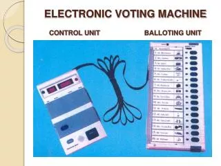
Units • Each Unit has been provided a casing. • Once opened 3 things will be found: Control unit, Ballot Unit and the Interconnecting Cable. Control Unit Ballot Unit Cable
Battery • They are Special batteries supplied separately • These batteries have a Seal which should be removed before Using • They have an active lifetime of 24 hours.
DETAILS of Units • Ballot Unit • Used by Voters for casting their votes. • It consists of : Ready Lamp BJP Candidate buttons(16) Congress Interconnecting Cable Candidate lamps(16) Ballot paper Screen
Details of Interconnecting Cable • It is a flat protected cable and who’s one end is connected to the Ballot Unit permanently while the other end is attached VIA a connector to the Control unit. • Make sure that the cable is properly secured to the Control unit. Cable TOP 15 PIN CONNECTOR SPRING CLIPS
Details of Ballot Unit • Ready lamp glows GREEN when Ballot button on Control Unit is pressed by P.O. to enable voting. Goes Off when voter has finished casting his vote. • Slide Switch Panel used to set anyone of the 4 options: 1,2,3,or 4. ie. For 1 ballot unit Switch is set to 1 and so on… • Candidates lamp: glows RED when the voter has pressed the candidate button pertaining to the candidate of his choice. • Ballot paper Screen: where the Ballot Paper with name, sr,no., Symbol of contesting candidates is inserted. • Masking tabs provided under the Candidate buttons. So depending on the no. of candidates contesting, the tabs are unmasked. Ones not in use are masked.
2.Control Unit • Controls the polling process. • Operated only by P.O. • Consists of: Display Section Busy lamp ON lamp Candidate Set Section 4 sections in all Result Section Ballot Section
Details of Control Unit • Display section has: 2 lamps: On and Busy ; also 2 display panels: one of 2 digit and other of 4 digit displays. • Candidate Set Section: has a cover opening l-r: we see a left compartment which accommodates the Battery and the right one a Red Cad Set button. This section is closed by thread Seal. • Result Section: also has same cover as above. On opening we find the left side has aBlack Close button while right side has inner compartment with its own door. One button her is result 1 button. used for one type of election only: like only single Poll. Result 2 used for both types conducted at the same time, Clear button. Provision kept for a seal in the cover of this inner compt. and thread seal too. • Ballot Section: has 2 buttons , a gray Total button and a large Ballot button. • Bottom of C.Unitalso open for plugging the cable from b.unit and a power switch to switch EVM On/Off.
Lamps details…. • On lamp: in display section will glow GREEN when Control Unit Power switch is put ON, indicating EVM is ready for use. • Busy lamp: in display section glows RED when Ballot button is pressed by P.O. to enable voter to cast vote. Goes Off when over.
Display Panel details 2 DIGIT DISPLAY • LE: link error: ie. Interconnecting cable not properly connected. • PE: Pressed error, where any of the candidates buttons in Ballot unit are jammed or kept pressed. • Er: Memory Error: Control unit not fit to use.
Display Panel details 4 DIGIT DISPLAY • no: indicates a button pressed on Control unit is pressed out of sequence. • End: End of display sequence after pressing Close , Result or clear button. • Full : indicates max no.of votes for which machine is designed. 9999 is the max.
Display on both panels • nP 1 : machine set for Single poll only. • Cd 6 : machine set for 6 candidates. • to 1234: total no. of votes casted = 1234 • 06 234: candidate 6 has 234 votes in his favor.
Beeps • A beep of not less than 2 seconds after a voter casted his vote. • A beep of 1 second, when displaying information on display units. • Short interrupted beeps to show malfunctioning , disconnection, errors….
Control Unit buttons • Cand Set: used to set EVM for no. of candidates contesting the election. • Clear: pressed before start of a poll: to clear machine of recorded informations. Used when election is over/ not done w/o orders. • Ballot: enables voter to record his vote: so once pressed: the BUSY lamp goes Red, Ready lamp of C.Unit goes Green and voter can now caste his vote. Then Pressed again to allow next voter to record his vote…. • Total: shows no. of candidates and total no. of votes recorded so far. Pressed at anytime: to see the same. But not when Busy lamp is ON. • Close: Once pressed: no further voting can take place. Only pressed at the end of the Poll. When Pressed the no. of polls, no. of candidates, total votes polled and the word end will be displayed. • Result: when EVM is used for simultaneous poll: ie Lok Sabha & Legislative assembly polls , both Result 1 & 2 are used ie. R1 for Loksabha,R2 for LA. When only single Poll, only R1 is used. In our case Only Result 1 USED. When Pressed it will display in sequence the no. of candidates, total no. of votes polled, votes for each candidates. The finally displays END. This button can be pressed as reqd.
SEQUENCE OF BUTTONS TO BE PRESSED ON CONTROL UNIT CAND. SET RESULT 1 CLOSE CLEAR RESULT 2 BALLOT
The EVM as it looks….. Ballot Unit Control Unit