InAs Inserted Channel HEMT
220 likes | 629 Vues
InAs Inserted Channel HEMT. 2003-21667 MDCL 이 종 원. Contents. I. Introduction II. The Design of Subchannel of InAs III. Normal VS Inverted HEMT IV. AlSb/InAs HEMT Growth on S.I. GaAs. Overview of InGaAs HEMT. Advantage for use in low noise and high frequency device

InAs Inserted Channel HEMT
E N D
Presentation Transcript
InAs Inserted Channel HEMT 2003-21667 MDCL 이 종 원
Contents I. Introduction II. The Design of Subchannel of InAs III. Normal VS Inverted HEMT IV. AlSb/InAs HEMT Growth on S.I. GaAs
Overview of InGaAs HEMT • Advantage for use in low noise and high frequency device • their high electron mobility & high sheet carrier density & high saturation drift velocity if the InAlAs/InGaAs 2DEG system • Conventional InP HEMT structure : high contact and gate electrode can cause large parasitic source and drain resistances (by the large conductance band discontinuity between the InGaAs cap layer and InAlAs layer, forming a barrier in the current flow between these layers)
I. Introduction • Why? I. Superior to GaAs or InGaAs channel devices a) their low-field mobility b) higher-lying satellite valleys c) deeper quantum well depth d) higher overshoot velocity II. Scaling Factor (for sub 0.1um device) • As Lg decreases, an appropriate aspect ratio has to be maintained to alleviate short channel Effect. • Also, Channel thickness has to be reduced for proper aspect ratio (∵ The thinning of barrier layer is limited by current tunneling) • Disadvantage ( Reducing of sheet carrier density in a channel and Undesired scattering phenomena because of hetero-junction interface and the enhancement of ionized dopant in supply layer)
InAs Inserted Channel HEMT • Conventional InP HEMT vs InAs Inserted HEMT (Ref. 1) Cap n In0.53Ga0.47As n In0.53Ga0.47As/In0.52Al0.48As Cap n In0.53Ga0.47As n In0.53Ga0.47As/In0.52Al0.48As Barrier I In0.52Al0.48As Delta-doping Barrier I In0.52Al0.48As Spacer i In0.52Al0.48As Spacer i In0.52Al0.48As Channel i InxGa1-xAs Channel i InxGa1-xAs Channel i InAs Channel i InxGa1-xAs Buffer i In0.52Al0.48As Buffer i In0.52Al0.48As InP Substrate InP Substrate Conventional InP HEMT InAs Inserted HEMT
Carrier Transport Characteristic • (Ref. 6) c) Conventional Composite chanel HEMT a) Modified Composite Channel b) Conventional InGaAs HEMT
Issue of the InAs Inserted HEMT I. The Design of Subchannel of InAs for composite channel (dependence of a) Temperature & Thickness b) Enhancement of carrier transport ) II. The Normal and Inverted HEMT Structure III. AlSb/InAs HEMT (The Growth on S.I GaAs )
Physics • The Basic Idea of Composite Channel • Low field channel region => electrons are mostly located in the high-mobility, small bandgap InGaAs layer • High field channel region => The energy of the electrons increases and more and more electrons populate the InP layer => Because of the larger bandgap, the rate of impact ionization in InP is smaller compared to that in the InGaAs channel => While the low-field mobility of InP is smaller than that of InGaAs, the high-field transport properties, especially the saturation velocity, are better in InP
Physics • Band Structure Calculation and Electron Transport (Ref.2) • Γ-valley mass of strained InAs (parallel<Perpendicular) • => The strain brings about an increase of the InAs band gap of 0.12eV
Physics • Monte Carlo Simulation • Include polar optical phonon scattering and inter-valley deformation potential scattering at 300K 26% enhancement 16% enhancement The reduction of slope Wide Γ-L band separation in InAs =L enhancement of electron heating Over 7kV/cm Electron energy of strained InAs> unstrained InAs => Smaller effective mass L & X valley of strained InAs => Higher energy
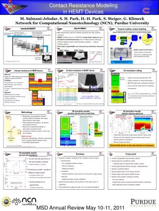
II. The Design of Subchannel (Ref.3) a)Mobility tested the function of Z and Lw b) This test’s result is Z=3nm and Lw=4nm (Consideration of Carrier Modulation and Short Channel Effect) => 13000cm2/Vs
II. The Design of Subchannel • The Thickness of InAs Inserted HEMT (Another Test) (Ref. 4) • Double Sided Delta-doping을 이용 (for low output conductance and kink-free I/V Characteristic) a) The Enhancement of the electron transport property b) 47% electron mobility improvement 40% the effective electron velocity increment (@ 300K)
II. The Design of Subchannel • Design Issue (Ref.5) • 3.5% lattice mismatch of InAs on InP --- Structure A Structure B Cap n In0.53Ga0.47As n In0.53Ga0.47As/In0.52Al0.48As Cap n In0.53Ga0.47As n In0.53Ga0.47As/In0.52Al0.48As Barrier I In0.52Al0.48As Barrier I In0.52Al0.48As Spacer i In0.52Al0.48As Spacer i In0.52Al0.48As Channel i In0.53Ga0.47As Channel i In0.53Ga0.47As Channel i In0.7Ga0.3As Channel i In0.3Ga0.7As Channel i InAs Channel i InAs Channel i In0.7Ga0.3As Channel i In0.3Ga0.7As Channel i In0.53Ga0.47As Channel i In0.53Ga0.47As Buffer i In0.52Al0.48As Buffer i In0.52Al0.48As InP Substrate InP Substrate 17% population increment 10% gm increment 8% ft increment (A: 220 GHz B:238 GHz @0.1um Lg) Compressively strained channel Structure A Tensilely strained channel Structure B
II. The Design of Subchannel • AlAs/InAs Superlattice Structure (Channel Composition Modulation Transistor) (Ref. 7) • For high electron sheet carrier density and good carrier confinement and high electron transport • To improve the thermal stability of InP HEMT a) Epi-Structure b) Band Structure 0.2um T-Gate Mobility 18300 cm2/Vs ft=180GHz gm = 1370 ms/mm -0.12eV ->-0.17eV 20% improvement of electron confinement
III. Normal VS Inverted HEMT (Ref. 8) a) Normal InAs Inserted Channel HEMT : high output conductance and low breakdown voltage • InAs Inserted Channel Inverted HEMT : channel layer located on the carrier supply layer => low output conductance (∵ superior to electron confinement and smaller distance between gate and channel) C) Little kink-effect and a high breakdown voltage
III. Normal VS Inverted HEMT • The enhancement of mobility characteristic • The scattering cased by ionized donor and interface roughness Low effective mass and high mobility in Inverted HEMT
AlSb/InAs HEMT (ref. 9) a) For high speed and low bias application (∵ high electron mobility and velocity, high sheet charge density and good carrier confinement) b) Disadvantage: charge control problem associated with impact ionization in the InAs channel (will increase as the Lg is reduced due to the higher fields present) b) Band Structure a) Epi-Structure
IV. AlSb/InAs HEMT 6.1A lattice constant AlSb/InAs conduction band discontinuity 1.35eV • Lattice Matched System (Ref. 10) I. Current Status 1. Epitaxial Growth Buffer (interface roughness scattering) 2. Impact Ionization Effect a) dominant for short gate-length when the drain bias exceeds the energy bandgap in the channel => Thinner channel scheme (kink effect and low output conductance, transconductance and peak current density) need for trade-off of channel thickness and device performance.
IV. AlSb/InAs HEMT • 개선방안 a.Need a good buffer for good surface morphology and good carrier transport characteristic b. Thin InAs channel thickness
Conclusion I. Design of Subchannel Band a. InAs thickness for high speed and carrier confinement b. for better performance high sheet carrier density and mobility and carrier confinement (In0.8Ga0.2As/InAs/In0.8Ga0.2As channel) ∵ 3.5 % InAs mismatch in the channel • For Low kink effect and high breakdown voltage and the improvement of carrier mobility and sheet carrier density => Inverted HEMT III. For low cost and similar bandgap engineering compared with InP HEMT => AlSb/InAs HEMT
InAs Inserted HEMT • Reference 1. Modern Microwave Transistors theory, Design, and performance Frank Schwierz Juin J. Liou Wiley-Interscience 2. First principles band structure calculation and electron transport for strained InAsHori, Y.; Miyamoto, Y.; Ando, Y.; Sugino, O.;Indium Phosphide and Related Materials, 1998 International Conference on ,11-15 May 1998 Pages:104 - 107 3. Improved InAlAs/InGaAs HEMT characteristics by inserting an InAs layer into the InGaAs channelAkazaki, T.; Arai, K.; Enoki, T.; Ishii, Y.;Electron Device Letters, IEEE ,Volume: 13 ,Issue: 6 ,June 1992 Pages:325 - 327 4. MBE growth of double-sided doped InAlAs/InGaAs HEMTs with an InAs layer inserted in the channel• ARTICLEJournal of Crystal Growth, Volumes 175-176, Part 2, 1 May 1997, Pages 915-918 M. Sexl, G. Böhm, D. Xu, H. Heiß, S. Kraus, G. Tränkle and G. Weimann 5. Impact of subchannel design on DC and RF performance of 0.1 μm MODFETs with InAs-inserted channelXu, D.; Osaka, J.; Suemitsu, T.; Umeda, Y.; Yamane, Y.; Ishii, Y.;Electronics Letters ,Volume: 34 ,Issue: 20 ,1 Oct. 1998 Pages:1976 - 1977 6. High electron mobility 18,300 cm2/V·s InAlAs/InGaAs pseudomorphic structure by channel indium composition modulationNakayama, T.; Miyamoto, H.; Oishi, E.; Samoto, N.;Indium Phosphide and Related Materials, 1995. Conference Proceedings., Seventh International Conference on ,9-13 May 1995 Pages:733 - 736
InAs Inserted Channel HEMT 7. InAlAs/InGaAs channel composition modulated transistors with InAs channel and AlAs/InAs superlattice barrier layerOnda, K.; Fujihara, A.; Wakejima, A.; Mizuki, E.; Nakayama, T.; Miyamoto, H.; Ando, Y.; Kanamori, M.; Electron Device Letters, IEEE ,Volume: 19 ,Issue: 8 ,Aug. 1998 Pages:300 - 302 8. Improving the characteristic of an InAlAs/InGaAs Inverted HEMT by inserting an InAs layer into the InGaAs channel Solid State Electronics vol. 38 NO. 5 pp997-1000 1995 Tatsushi Akazaki, Tatamoto Enoki, Kunihiro Arai and Yasunobu Ishi 9. 0.1um AlSb/InAs HEMTs with InAs subchannel Electronics Letters 23rd July 1998 Vol. 34 No.15 J.B boos, M.J. Yang, B.R. Bennett, D. Park, W. Kruppa, C.H. Yang and R. Bass 10.InAs channel HFETs: current status and future trends Bolognesi, C.R.; Signals, Systems, and Electronics, 1998. ISSSE 98. 1998 URSI International Symposium on ,29 Sept.-2 Oct. 1998 Pages:56 - 61