Download
1 / 26
330 likes | 889 Vues
Explore the various fuel feed systems in diesel and petrol engines, including gravity, pressure, vacuum, pump, and injector systems. Understand the operation of fuel tanks, filters, carburetors, MPFI, pumps, gauges, and more.

E N D
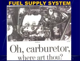
Introduction of fuel feed system To run an automobile engine, either diesel an petrol engine the fuel reaches from the fuel tank. And the petrol fuel tank reaches through the fuel pump, filter and carburetor to the engine. Carburetor is not needed, the fuel is injected into the engine cylinder by an injector.
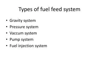
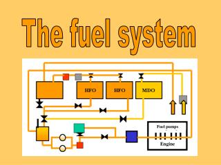
The fuel feed system:- Gravity system Pressure system Vacuum system Pump system Fuel injector system
Gravity system :- in gravity system of fuel feed, the fuel tank is mounted at a place higher than that of carburetor. The fuel flows from the tank to the carburetor due to gravitational force and it is cheap and simple system the fuel tank is directly connected to the carburetor. Scooters and motor cycles makes use this system .
Pressure system:- In pressure system, a pressure seal tank is used the pressure is created in the tank by means of a separate air pump. The pump is primed by cam which produces pressure in tank and the fuel flows to the carburetor. the tank can be placed above or below the carburetor.
Vacuum system:- In vacuum system, the engine suction is used for sucking the fuel from the main to the auxiliary fuel tank from where it flows by gravity to the carburetor.
Pump system:- In pump system, a fuel pump is used to feed the fuel from the fuel tank to the carburetor. The pump is driven either by the camshaft or electrically. In this system the fuel tank can be placed at any suitable position in vehicles.
Fuel injector system:- In fuel injection system, a fuel injection pump is used in placed of carburetor . The fuel is atomized by means of a nozzle and then delivered into an air steam. separate fuel injection system is used for each cylinder which controls the mixture under different load and speed conditions.
overview of fuel feed system:- 1)The fuel tank 2)The Fuel Filter 3)carburetor 4)MPFI, 4)The Fuel Pump Mechanical Fuel Pump Electric Fuel Pump Fuel 5)Fuel Gauges 6)Fuel Lines 7) Air Cleaners
Fuel Tank:- The fuel tank stores the excess fuel until it is needed for operation of the vehicle. The fuel tank has an inlet pipe and an outlet pipe. The outlet pipe has a fitting for fuel line connection and may be located in the top or in the side of the tank. The bottom of the tank contains a drain plug.
Fuel Filter :- To ensure this cleanliness, fuel filters are installed in the fuel line. Fuel filters can be located at any point between the fuel tank and the carburetor. One may be in the tank itself, in the fuel pump or in the carburetor. Any water or solid material which is trapped by the filter will fall to the bottom of the glass bowl .
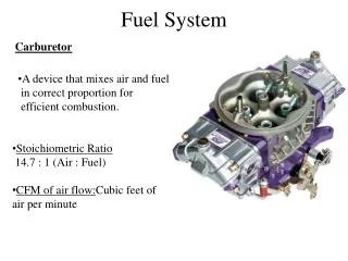
Concept of carburetion The carburetor is atomizing and vaporizing the fuel and mixing it with the air in varying proportions to the suit the changing conditions of spark ignition engines.
Working of carburetor The throttle (accelerator) linkage does not directly control the flow of liquid fuel. Instead, it actuates carburetor mechanisms which meter the flow of air being pushed into the engine. The speed of this flow, and therefor its pressure, determines the amount of fuel drawn into the airstream. The carburetor has following components which given below:- Venture tube Throttle valve Metering system
multi point fuel injection (MPFI):- The MPFI is a system or method of injecting fuel into internal combustion engine through multi ports situated on intake valve of each cylinder. It delivers an exact quantity of fuel in each cylinder at the right time. there are three types of MPFI system –batched, simultaneous and sequential.
Advantages of MPFI system:- The MPFI system encourages effective fuel utilization and distribution . It improve functionality and durability of engine component. The MPFI engine vibrate less and do not required to be cranked twice or thrice in cold weather. The MPFI automobile technology improve the engine response during sudden acceleration and deceleration.
Fuel Pump :- The fuel pump has three functions: to deliver enough fuel to supply the requirements of an engine under all operating conditions, to maintain enough pressure in the line between the carburetor and the pump to keep the fuel from boiling. Excessive pressure can hold the carburetor float needle off its seat, causing high gasoline level in the float chamber.
MECHANICAL FUEL PUMP pulling the lever and diaphragm down against the pressure of the diaphragm spring and producing suction (vacuum) in the pump chamber. The suction will hold the outlet valve closed and pull the inlet valve open.
Electric Fuel Pump The electrically driven turbine type of pump, first used on the Buick Riviera, was a great departure from the usual fuel pump design. It uses a small turbine wheel driven by a constant speed electric motor.
Fuel Gauge:- A fuel gauge is used to indicate to the driver the level of the fuel in the tank. Fuel gauges are usually of the following types:- AC electric fuel gauge with balanced coils bimetal type electric fuel gauge Thermal type electric fuel gauge Thermostatic type electric fuel gauge.
1.AC electric fuel gauge with balanced coils:- It consist of two unit tank unit and dash unit .The two unit are connected by a single wire . Tank unit comprises a rheostat and float . The rheostat contact is actuated by float to assume a position on the resistance corresponding to the position of float in the fuel tank.
2.bimetal type electric fuel gauge:- It also consists of two units-The sender and dash unit(receiver unit). The sender unit is located in the tank.it consist of heating coil wound around a bimetal strip and on external float mechanism which acts through a cam and flexible diaphragm. which turn varies the tension in the bimetal strip.
Fuel Lines :- Fuel lines, which connect all the units of the fuel system, are usually made of rolled steel or, sometimes, of drawn copper. The Fuel lines are placed as far away from exhaust pipes. o that excessive heat will not cause vapor lock. They are attached to the frame, the engine.
Air Cleaners:- Air cleaners are made to separate dust and other particles in the incoming air before it enters the carburetor. e if it is not filtered and cleaned. Dust and other foreign materials in the engine will cause excessive wear and operating problems.
Wet cleaner:- It use for cleaning the atmospheric air. It consists of wire mesh filtering element which is coated with in oil fill . This type of air cleaner should be clean periodically about every 8000 km.