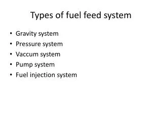
Types of fuel feed system
900 likes | 2.18k Vues
Types of fuel feed system. Gravity system Pressure system Vaccum system Pump system Fuel injection system. Types of fuel pumps. Mechanical fuel pump Electrical fuel pump. Types of Carburettor. According to the arrangement of float chamber: Eccentric and Concentric

Types of fuel feed system
E N D
Presentation Transcript
Types of fuel feed system • Gravity system • Pressure system • Vaccum system • Pump system • Fuel injection system
Types of fuel pumps • Mechanical fuel pump • Electrical fuel pump
Types of Carburettor According to the arrangement of float chamber: • Eccentric and • Concentric According to the number of units • Single • Dual and • Four-barrel According to the type of metering system • Air-bleed jet and • Metering rod type According to the type of power system • Manually operated and • Vacuum controlled
Types of Carburettor According to the type of venturi - Plain venturi, - Double venturi, - Vane venturi, - Nozzle-bar venturi and - Triple venturi Depending upon the direction of air flow or forms of Carburettors: a) Up-drought b) Horizontal c) Down-drought Carburettors.
Types of Carburettor Depending on the method of varying the mixture strength or choke area carburettors are classified as: 1.Open Choke or Constant Choke carburettor The mixture strength is determined by the varying depression of a fixed tube or venturi Eg: solex and zenith 2.Variable Choke or Constant Depression or Constant Vaccum carburettor Depression in the choke tube is reasonably constant and the size of the jet is varied to provide the correct mixture for all engine operating conditions. Eg: S.U. carburettor
Simple Carburettor • Venturi • Throttle valve • Metering system
Various systems or circuits in the carburettor • Float system • Idling and low speed system • High speed system • Power system • Anti-percolator • Accelerating pump system • Choke system
Float system AIR CLEANER CHOKE VENTURI Float Valve Float Arm Float Chamber Float THROTTLE VALVE
Idling and low speed system • Rich mixture is needed- 10:1 • It consists of idle passages for fuel and air • Idling system – starting, idling and low speeds • Cut off when speed increases to about 40kmph
High speed system • Throttle valve is sufficiently opened • Faster air flow through the air horn and greater the vacuum created in the venturi • Additional fuel will be discharged • This system comes in action as soon as the engine speed increases from 33 KMPH
Power system • When the engine is under strain requiring more power, a richer, a more powerful mixture • Power system is either manually operated or vacuum controlled
Anti-percolator • This device is to relieve the vapour pressure that develops in the carburettor due to the vaporization of fuel in hot weather • This pressure causes flooding of fuel • This valve relieves the pressure by venting the passage in the discharge nozzle to the atmosphere
Accelerating system • For rapid acceleration, additional fuel must be delivered by carburettor • Quick opening of throttle valve • Produces leaner mixture instead of being richer • Accelerating pump is used to provide correct A-F mixture, discharges directly into mixing chamber
Choke • For starting the cold engine, a rich mixture is needed • Choke is operated to shut off the air supply to carburettor • During the suction stroke less amount of air, and more amount of fuel is sucked thus a rich mixture is obtained • After starting the engine choke should be opened to atmosphere– else flooding
Constant Choke or C.C. Carburettor • Here the main orifice known as the choke tube or venturi is of fixed dimensions and metering is affected by varying the pressure drop across it. e.g • Solex carburettor • Zenith carburettor • Carter carburettor • Stromberg carburettor
Working of Solex Carburettor • Starter • Consists of a starter valve in the form of flat disc having holes of different sizes • These holes connect the petrol jet and starter jet sides to the passage which opens to air horn • Starter lever is operated by the driver • At starting bigger holes are connected • After starting smaller holes • Later in off position
2. Idling and low speed operation • From the lower part of the well of the emulsion system a hole leads off to pilot jet(13) • At idling throttle partly closed and engine suction is applied at pilot jet. Fuel from the pilot jet mixes with small amount of air from the small pilot air bleed orifice(14) • The rich mixture for idling is discharged into the throttle body past the idling control screw(15). • By-pass orifice(17) provided on the venturi side of the throttle valve ensures smooth transfer of idle and low speed circuit to the main jet circuit .
3. Normal running • During normal running, the throttle valve is partly opened and the engine suction is applied at the main jet, which supplies the fuel • Air enters directly through the venturi and mixes with the fuel • The air-fuel mixture is governed by the throttle valve
4.Acceleration: • A diaphragm type acceleration pump supplies extra fuel needed for acceleration through pump injector • Pump lever is connected to the accelerator so that pressing the pedal, the lever moves towards the left, pressing the membrane towards the left, thus forcing the petrol through pump jet and injector. • On making the pedal free, the lever moves the diaphragm back towards right creating vacuum towards left which opens the pump inlet valve and thus admits the petrol from the chamber into pump.
Zenith carburettor 3 jets Main jet, compensating jet (around main jet) and idling jet Choke valve is used for starting Idling and slow speed running the air enters through the holes Mixes with the fuel in idling passage and passes to the idling jet
A separate knob is provided for idle adjustment i.e., supply of mixture • When the throttle valve is widely opened, the main jet comes into action along with idling jet • On further opening the throttle valve, the whole suction is applied on the main and compensating jet and idling jet is cut off • The compensating jet takes care of A-F correct ratios at different speeds
Carter Carburettor • Float circuit • Starting circuit • Idle and low speed circuit • Part throttle circuit • Full throttle circuit • Acceleration pump circuit
Constant Depression or C.D. Carburettor or constant vacuum type • SU CARBURETTOR SU Carburetters (named for Skinners Union, company that produced them) were a brand of carburettor usually of the side draught type but down draught variants were also used.
Working of SU carburettor • It is a constant vacuum or depression type with automatically variable choke or venturi • The mixture compensation is achieved by maintaining constant vacuum over the jet and varying the effective size of the jet • It is a horizontal type of carburettor • Spring loaded piston controls the air passage which is in the form of rectangular opening of constant width and adjustable height • The position of piston at any instant depends upon the balance of it’s own weight against vacuum force • As piston weight is constant, vacuum also remain constant • Consists of single jet in which a tapered needle operates • A tapering needle is fixed to the piston
Area of throat is varied by means of a piston which slides up and down • When accelerator is operated the piston moves up and down to control the air supply • And there by needle moves up and down in the jet controlling the fuel supply • Piston moves up throat area increases and air flow increases • Also needle moves up area of jet increases and fuel flow increases • Similarly it reduces and maintain correct A-F mixture at different operating conditions • Used in racing cars, scooters and motor cycles • No separate idling or acceleration device is used
Petrol Injection • Petrol is supplied into intake manifold through petrol Injectors . This process is called the petrol injection. • The petrol is received by the injector from the pump and is sprayed into the air stream in atomized form. Adv: • High power • Quick starting and warm up • Low specific fuel consumption • No necessity to maintain a stable ignition mixture in the manifold • No necessity of induction heating
Free from icing trouble • Avoidance of acceleration disturbances during cornering and braking • Quick starting and warm-up • Greater freedom in choice of fuels Dis adv: • Higher initial cost • Higher maintenance cost • Complicated design • Difficult in operation • Difficult servicing
Types According to location of injector • Cylinder or direct injection system • Port injection system and • Manifold or throttle body injection According to control method • Mechanical injection • Electronic injection According to number of injectors • Multi point injection system • Single point injection system
In port injection the Injector is placed on the side of the intake manifold and sprays petrol into the air inside the intake manifold. The petrol mixes with air completely. This mixture of petrol and air then passes through the intake valve and enters into the cylinder.
Single point fuel injection • Single Injector is placed slightly above throat of the throttle body. The Injector sprays petrol into the air in the intake manifold where petrol mixes with air. • This mixture then passes through the throttle valve and enters the intake manifold.
Octane number • The anti-knock value of fuel is measured in octane number rating (ONR). • The fuel iso-octane is highly knock resistant and it is rated 100 • Normal heptane (n-heptane) knocks easily and it is rated zero • The percentage of iso-octane by volume in a mixture if iso-octane and n-heptane, which exactly matches the knocking intensity of a given fuel in a standard engine under prescribed operating conditions is termed as “Octane Number” of the fuel
Cetane number • The cetane number of diesel fuel refers to the ease with which the fuel ignites • The best diesel fuel is that which ignites readily and burns steadily and rapidly • It is rated by means of a scale called cetane rating • The cetane number assigned to a diesel fuel is a mesure of its ignition qualities compared to those of a standard fuel, normal cetane (C16H34) • Lower the cetane number there is more possibility of fuel to knock
Fuel Injection System in Diesel Engines Functions of a Fuel injection system: • Filter the fuel • Measure the correct quantity of fuel to be injected • Time the fuel injection • Control the rate of fuel injection • Atomize the fuel • Distribute the fuel in the combustion chamber
Air blast injection • In this method the, air is compressed in a compressor to high pressure and injected air blast along with fuel into the cylinder. • The rate of fuel admission can be controlled by varying the pressure of injection air. • Used in large stationary and marine engines Adv: • It provides better atomization and distribution of the fuel • As the combustion is more complete the BMEP is higher • Inferior fuels can be used
Dis Adv: • It requires high pressure multi stage compression • A separate mechanical linkage is required to time the operation of fuel valve • Due to compression and linkage the size of the engine increases • Since the fuel burns very near to the nozzle it is overheated
Airless or Solid Injection • In this method the fuel under high pressure is directly injected into the combustion chamber • It burns due to the heat of compression of the air • This method requires a fuel pump to deliver the fuel at high pressure- 300kg/cm2 • This method is used for all types of small and big diesel engines
Types of modern airless or solid fuel injection system: • Common Rail Injection System • Individual Pump Injection System • Distributor System
COMMON RAIL INJECTION SYSTEM A single pump supplies high pressure fuel to header, a relief valve holds the pressure constant. The control wedge adjusts the lift of mechanically operated valve to set amount and time of injection.
Adv: • System is simple and less maintenance cost • Only one pump is sufficient for multi cylinder engine • It fulfills requirements of either constant load with variable speeds or variable loads with constant speed • Variation in pump supply pressure effects all the cylinders equally Dis adv: • Leaks in the injection valve • Accurate design and workmanship is required
Individual pump injection system • In this system an individual pump or pump cylinder connects directly to each fuel nozzle. • Pump meters charge and control injection timing.
Each cylinder has its own individual high pressure pump and metering unit • It is quite compact method and involve higher cost Dis adv: • This system has to be designed accurately to pump small quantity of fuel
Distributor System • In this system the fuel metered at a central point, a pump pressurizes, meters the fuel and times the injection. • From here fuel is distributed to cylinders in correct firing order by cam operated poppet valves which open to admit fuel to the nozzles.